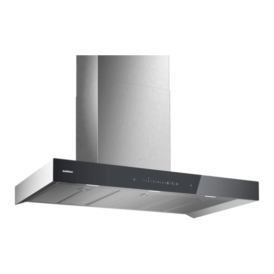
Gaggenau AW240191 User Manual And Installation Instructiions - Page 15
Browse online or download pdf User Manual And Installation Instructiions for Ventilation Hood Gaggenau AW240191. Gaggenau AW240191 20 pages.

egory III and according to the installation
regulations.
▶ When installing the appliance, check that
the power cable is not trapped or dam-
aged.
15.4 General information
Follow these general instructions during the installation.
¡ For the installation, observe the currently valid build-
ing regulations and the regulations of the local elec-
tricity and gas suppliers.
¡ When discharging the exhaust air, the official and
legal regulations, such as the regional building
code., must be observed.
¡ In order to freely access the appliance for servicing,
select an easy-to-reach installation site.
¡ The surfaces of the appliance are sensitive. Avoid
damaging them during installation.
15.5 Instructions for the electrical
connection
In order to safely connect the appliance to the elec-
trical system, follow these instructions.
WARNING ‒ Risk of electric shock!
It must always be possible to disconnect the appliance
from the electricity supply. The appliance must only be
connected to a protective contact socket that has been
correctly installed.
The mains plug for the mains power cable must be
▶
easily accessible after the appliance is installed.
If this is not possible, an all-pole isolating switch
▶
must be integrated into the permanent electrical in-
stallation according to the conditions of overvoltage
category III and according to the installation regula-
tions.
The permanent electrical installation must only be
▶
wired by a professional electrician. We recommend
installing a residual-current circuit breaker (RCCB)
in the appliance's power supply circuit.
Sharp-edged components inside the appliance may
damage the connecting cable.
Do not kink or trap the connecting cable.
▶
¡ The connection data can be found on the rating
plate. → Page 11
¡ The connecting cable is approx. 1.30 m long.
¡ This appliance complies with the EC interference
suppression regulations.
¡ The appliance corresponds to protection class 1.
You should therefore only use the appliance with a
protective earth connection.
¡ Do not connect the appliance to the power supply
during installation.
¡ Ensure that the protection against contact is guaran-
teed during installation.
15.6 Information on the installation situation
¡ Install this appliance on the kitchen wall.
¡ To install additional special accessory parts, ob-
serve the enclosed installation instructions.
¡ The appliance must be installed with no more than
one side directly next to a high-sided unit or a wall.
The distance between the appliance and wall or
high-sided unit must be at least 50 mm.
¡ The width of the extractor hood must correspond at
least with the width of the hob.
¡ To optimally detect the cooking vapours, install the
appliance in the middle of the hob.
15.7 Instructions for the exhaust air pipe
The appliance manufacturer does not provide any war-
ranty for faults attributable to the pipeline.
¡ Use a short, straight exhaust air pipe with as large a
pipe diameter as possible.
¡ Long, rough exhaust air pipes, many pipe bends or
small pipe diameters reduce the suction power and
increase the fan noise.
¡ Use an exhaust pipe that is made of non-combust-
ible material.
¡ To prevent condensate from returning, fit the ex-
haust pipe with a 1° gradient from the appliance.
15.8 Instructions for the air extraction mode
For air extraction mode, a one-way flap should be in-
stalled.
Notes
¡ If a one-way flap is not included with the appliance,
one can be ordered from a specialist retailer.
¡ If the exhaust air is conveyed through the external
wall, a telescopic duct should be used.
15.9 Installation
Checking the wall
Check whether the wall is vertical and has sufficient
1.
load-bearing capacity.
Drill the hole depth in accordance with the length of
2.
the screws.
The wall plugs must have a secure grip.
The screws and wall plugs enclosed are only suit-
3.
able for use with solid brickwork.
Suitable fasteners must be used for other structures,
e.g. plasterboard, aerated concrete, Poroton blocks,
masonry bricks.
The maximum weight of the appliance is 40 kg.
4.
Preparing the wall
Mark a vertical centre line on the wall from the ceil-
1.
ing to the lower edge of the appliance.
Ensure that there are no electrical wires, gas pipes
2.
or water pipes in the area where holes are to be
drilled.
Use the enclosed template to mark where the
3.
screws are to be inserted and the outline of the at-
tachment area.
Installation instructions en
15
