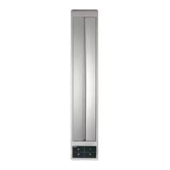
Gaggenau VL 431 Operating And Assembly Instructions Manual - Page 11
Browse online or download pdf Operating And Assembly Instructions Manual for Ventilation Hood Gaggenau VL 431. Gaggenau VL 431 16 pages. Hob ventilator

Installing the appliance
9 3
1 6 2
5
m in . 3
8 0
4 5 0
0
m in . 5
4 9 0
Blow-out opening:
downward or
at the side
5 1 0
1 4 0
8 2 0
1 2 8 0
140
50
135
If two
Vario appliances are used, the hob ventilator
must be installed between the appliances. If 4-plate
hobs are used, it is recommended to place two
ventilators to the left and right of the hob. Owing to
the high air output, an adequate supply of air is
required. If you have installed a gas appliance
between the hob extractors VL 430/431, the gas
hob has to be fitted with two air baffles LS 330 on
the side of the hob while cooking. The air baffles
not only improve the airflow of the extractor next to
a gas appliance, but also prevent a flame which has
been set to a low level from being extinguished.
If you have installed the hob extractor only on one
side of the gas appliance, it is sufficient to fit one
air baffle LS 330 on the side facing the extractor.
Note: do not install this appliance next to a
VG 411 gas cooker.
The hob ventilator is installed at the side of the
Vario appliance without any gap between the
appliances.
• As standard, the blow-out direction is downward.
Proceed as follows to establish a blow-out opening
at the side:
– Undo all 5 screws on the connection piece and
detach the connection piece.
– Undo the screws of the side cover.
– Screw the connection piece onto the side
opening and the cover onto the bottom opening.
• Cut out the recess for one or several Vario
appliances in your worktop. Proceed as indicated
on the installation sketch.
• Peel the protective film off the sealing tape. Stick
the sealing tape to the front and rear of the cut
out, so that half of the tape overlaps on the inside.
• On the side of the ventilator, press the seal into
the groove provided.
9
