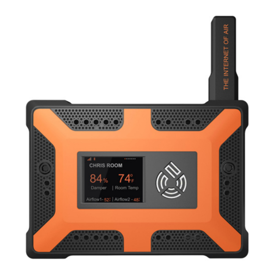
75F SMART DAMPER Installation & Operation Instructions
Browse online or download pdf Installation & Operation Instructions for Control Unit 75F SMART DAMPER. 75F SMART DAMPER 3 pages.

|
APPLICATION
The 75F Smart Damper is to be used as part of the Dynamic Airflow Balancing™
solution. The Smart Damper is where you will feed the 24VAC power bus line
from your power supply. The Smart Damper will also power a Wireless Room
Module (WRM), Wireless Ceiling Module (WCM), or a Remote Temperature
Sensor (RTS) through the provided Damper Harness.
|
PRECAUTIONS
When installing multiple dampers in a zone only provide the 24VAC
power bus line to one of the two dampers. (A zone constitutes a WRM,
WCM, or RTS).
Failure to wire devices with the correct polarity when using a shared
transformer may result in damage to any device powered by the shared
transformer.
Disconnect power before installing. Never connect or disconnect wiring
with the power applied.
Do not run the low voltage wiring in any conduit with line voltage.
Be sure RPPT is accessible for wiring.
|
FEATURES
24VAC power pass-through
Modulation of airflow through the duct controlled by the 75F Dynamic
Airflow Balancing™ solution
|
SPECIFICATIONS
Smart Damper
Supply Voltage: 24VAC
Operating Environment: 41°F – 122°F
Dimensions: (H) 6"; Diameter 6, 8, 10, 12", or custom sizes
Enclosure: Metal sheath
|
MOUNTING
INSTALLATION & OPERATION INSTRUCTIONS
www.75f.io
SMART DAMPER | RADIAL
+1 (651) 998-4080
