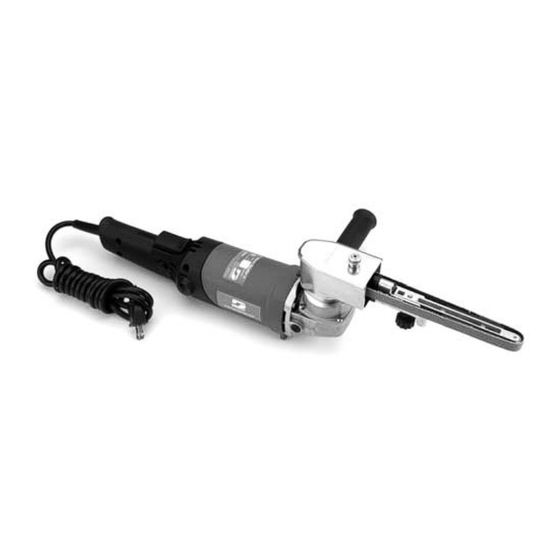
Dynabrade 40601 Safety, Operation And Maintenance Instructions - Page 5
Browse online or download pdf Safety, Operation And Maintenance Instructions for Tools Dynabrade 40601. Dynabrade 40601 8 pages.

35
36
30
28
26
25
24
Definitions of Label Symbols
Symbol
Description
A . . . . . . . . . . . . . . . . . . . . .amperes
Hz . . . . . . . . . . . . . . . . . . . . . . . .hertz
. . . . . . . . . . .Class II Construction
n o . . . . . . . . . . . . . . . .no load speed
.../min . . . . . . . . .revolutions per min.
Index Key
No. Part #
Description
1 89300 Screw (3)
2 89301 Bearing Box
3 89333 Spindle
4 50677 Bearing
5 89306 Bearing Retainer
6 89307 Screw (3)
7 89309 Gear
8 01015 Bearing
9 89311 Shaft Lock Pin
10 89313 Screw (4)
To order replacement parts, specify model number and serial number of your machine.
Complete Motor Assembly
37
38
39
27
34
33
30
29
27
11 89351 Side Handle
12 89312 Thread Plug
13 89315 Spring
14 89316 Button
15 89314 Gear Box
16 89317 Nut
17 89318 Gear
18 89319 Bearing
19 89320 Bearing Retainer
20 89321 Screw
40
32
31
15
14
17
16
13
12
10
8
9
7
6
5
4
3
2
1
21 89417 Armature
22 89324 Bearing
23 89325 Bearing Holder
24 89409 Field Screw (2)
25 89408 Fan Baffle
26 89407 Field
27 89406 Field Lead (4)
28 89405 Field Case
29 42617 Specification Label
30 40404 Logo Label (2)
5
22
21
20
19
18
11
31 89415 Screw (4)
32 89416 Left Rear Cover
33 89404 Brush Holder (2)
34 89414 Brush (2)
35 89400 Brush Cap (2)
36 89401 Right Rear Cover
37 89402 Strain Relief
38 89403 Screw (2)
39 89418 Switch
40 89419 Power Cord
23
