Hi-Velocity RBM-50 Installation Manual - Page 8
Browse online or download pdf Installation Manual for Control Unit Hi-Velocity RBM-50. Hi-Velocity RBM-50 12 pages. Rbm refrigerant base module
Charging (Continued)
The RBM coil can operate at a level that is different from
most other conventional system coils. Typically, superheat levels
are slightly lower at 6-10°F (1 - 3°C) of superheat. Adjustment
of the valve also differs somewhat. Rather than having a large
effect on the range of superheat, adjustment of the valve has
a larger effect on the system pressures; superheat maintaining
a fairly constant point. Opening the valve will increase suction
pressures and decrease liquid pressures, while closing the valve
will decrease suction pressures and raise liquid pressures.
Typical Operating Ranges
Saturated Suction Temperature
Suction Line Temperature
Superheat
Suction Line Pressure (R-410A)
Liquid Line Pressure (R-410A)
Heat Pumps
Traditionally, SDHV systems have been charged to special
guidelines when used in conjunction with heat pumps. This
charging procedure involved charging the units to normal
cooling capacities and reviewing the operation in heating mode.
If head pressures were found to be impinging on the high head
pressure limits, a small amount of refrigerant was removed to
prevent the unit from shutting down. The cause of high head
pressures in heating mode is due to the disparity in sizes of the
indoor and outdoor coils, along with the lower airflow rates of
SDHV systems.
With the introduction of newer, larger heat pumps, this issue
is more likely to be experienced. While some heat pump units
may still be charged in the traditional method, the amount of
refrigerant that is required to be removed for heating mode may
leave the system drastically undercharged for cooling mode. For
this reason it is highly recommended that a Bi-Flow Receiver be
used with heat pump applications.
Bi-Flow Receiver
The Bi-Flow Receiver is designed
for use with heat pump systems,
up to 5 tons, and with any typical
refrigerants. The receiver provides
a location for the storage of excess
refrigerant during the heating cycle,
minimizing head pressures. During
cooling mode, the receiver is empty,
allowing the full refrigerant charge to
be utilized for cooling.
www.hi-velocity.com
34 - 40°F (1 - 4°C)
38 - 44°F (3 - 7°C)
6 - 10°F (1 - 3°C)
110-124 psig (7.5-8.5 bar)
250-300 psig (17-20.5 bar)
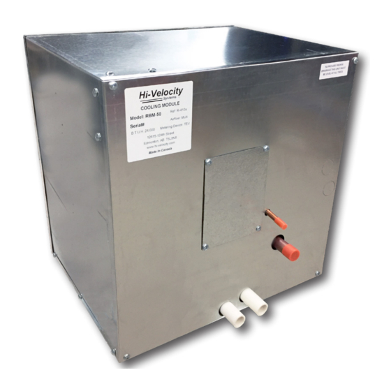
RBM Refrigerant Base Module Installation
The receiver is a horizontal tank with a pair of dip tubes
extending to the bottom of the tank. These two tubes allow for
liquid refrigerant to be drawn from the tank regardless of the
direction of flow. For this reason, the receiver must be mounted
so that the inlet/outlets of the tank come out of the top of the
unit. Mounting brackets are located at the base of the unit for
secure mounting. The receiver is to be located on the liquid line
of the system, anywhere between the indoor and outdoor coils.
As the unit is of a bi-flow design, it does not matter which end
faces towards the indoor coil.
The inlet/outlet ports are constructed of steel and require
the use of a 35-45% Silver Solder and Flux for brazing. The use
of standard copper to copper solders may result in difficulty
brazing and the potential for a failure at the weld. Ensure
that the tank is protected from overheating while brazing and
that any remaining flux is cleaned from the unit. If installing
outdoors, ensure that the receiver is insulated and protected
from the elements.
When designing the return air for a Hi-Velocity System, there
are a few things to consider. It is common to use centralized
return air with systems that have rooms that are within a
common area. Separate floors or rooms that have high loads
and require a large amount of supply air flow should have their
own return air, or be tied into the centralized return air to allow
the air to return back to the fan coil. Rooms or areas that cannot
be tied into the return air should have an air transfer grill to
allow the air to escape the room and flow back to a centralized
return air.
Important: Return Air must be filtered
before entering the cooling module.
-8-
-8-
Module RBM
Return Air
© 1995-2020 Energy Saving Products Ltd.
© 1995-2020 Energy Saving Products Ltd.