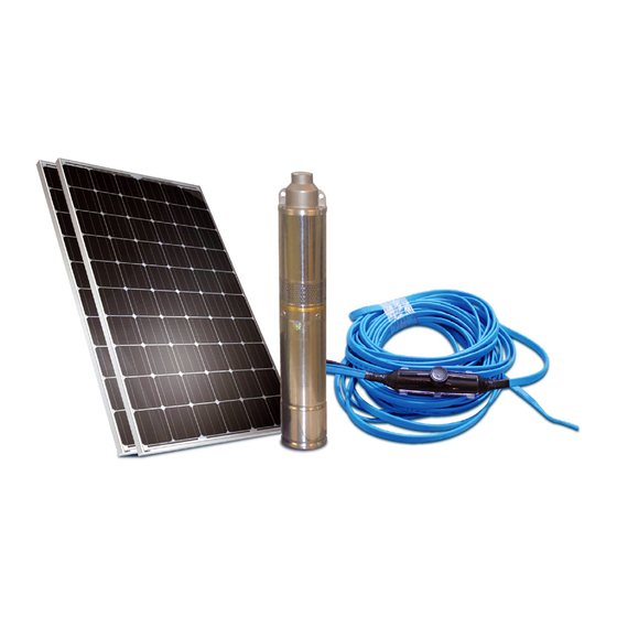
DAYLIFF SUNFLO-S 150 Installation & Operating Manual - Page 4
Browse online or download pdf Installation & Operating Manual for Inverter DAYLIFF SUNFLO-S 150. DAYLIFF SUNFLO-S 150 17 pages. Solar pumping systems

Congratulations on selecting a Dayliff SunFlo Solar Pumping System.
They are manufactured to the highest standards and if installed and
operated correctly will give many years of efcient and trouble free
service. Careful reading of this Installation Manual is therefore
important, though should there be any queries they should be
referred to the equipment supplier.
1. SPECIFICATIONS
1.1 PUMP
Solar Pumping Systems are available with several pump options as follows:-
SunFlo-S: Pumps are of positive displacement three-chamber diaphragm design and
can run dry without damage. An internal by-pass is incorporated to prevent damage in the
event of delivery cut-off.
Pump components are manufactured from high quality engineering plastic with
santoprene used for the diaphragm and EPDM for the valves. Casings are plastic for the
150 and stainless steel for the 300.
PV connection is either direct or through a charge controller that is connected to a battery
for 24hrs operation.
SunFlo- A: Pumps are of rotary screw design, the screw being made of stainless steel with
a rubber stator. They feature an in-built controller for starting and running the pump which
incorporates over and under current and voltage protection.
SunFlo-B: Pumps are of either rotary screw or centrifugal design depending upon model.
Material of construction for rotary screw design is stainless steel screw with rubber stator
while centrifugal pumps feature noryl impellers and stainless steel chambers.
Pumps are supplied with a self-contained multifunction MPPT (Maximum Power Point
Tracking) controller that provides high efficiency output, typically +25% higher than
conventional pumps of a similar water output. The controller also protects for over current,
over and under voltage and low water level (with provided electrode) and features
indicator lights that give the pump's operating status. The system can be optionally
installed with batteries so the pump operates when there is insufficient solar irradiation.
1.2 POWER OUTPUTS
Typical performance figures are given at standard test conditions of 1000W/m solar
irradiance and 25 C. Output will vary throughout the year depending upon prevailing
irradiation levels. For indicative purposes, factors of 1.1 can be applied for hot arid areas
and 0.9 for temperate high altitude areas in East Africa. Output will vary throughout the
day as a proportion of the estimated hourly irradiation as shown in Graph 2.
0
1
2
