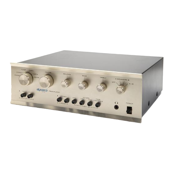
DYNACO PAT5PWR Assembly Manual - Page 11
Browse online or download pdf Assembly Manual for Amplifier DYNACO PAT5PWR. DYNACO PAT5PWR 18 pages. Replacement power supply rev e hardware

C7
470 µF
C10
470 µF
C11
470 µF
Check your work
Look over the board to verify that:
1. All components are soldered.
2. No solder bridges are apparent.
3. Polarity of the electrolytic capacitors is correct.
4. The right regulator is in the right location.
5. The heatsink hardware is tight.
6. Diode polarity is correct.
If everything looks good, you're ready to install the power supply into your PAT-5.
Checking the preamp and old power supply
For these steps, use your soup bowl to safely store the mechanical parts you'll remove as
you disassemble and re-assemble your PAT-5.
This section assumes that the original power supply and preamp was nominally working,
We'll measure the original voltages to confirm that assumption. Here are the steps.
Checking the preamp and old power supply
Pull the Preamp's AC plug and wait 1 minute before going on.
Remove the four black slotted-head screws, 2 on each side of the preamp,
that hold the top cover in place.
Remove the one screw from the center of the back of the top cover.
Remove the cover and set it aside.
Set your meter to DC volts.
Make sure that your PAT-5 is completely disconnected from any other
equipment.
Plug the PAT-5 into the AC power socket. Note: There are potentially lethal
voltages inside the PAT-5 from the instant it is plugged in, regardless of the
state of the ON-OFF switch!
Measure the voltage from eyelet 4 to eyelet 1. It should be 42.5 Volts, plus
or minus 3 Volts.
Measure the voltage from eyelet 3 to eyelet 1. It should be 15 Volts, plus or
minus 1.5 Volts.
Measure the voltage from eyelet 7 to eyelet 1. It should be -15 Volts, plus or
minus 1.5 Volts.
Voltages outside of the indicated range may indicate a problem with the original power
supply. Voltages less than the indicated amount (for example, if the -15 measured only -
3) might indicate either a problem with the original power supply, or a problem with the
PAT-5 circuits. If you have that condition, the next few instructions well help you sort it
out.
Electrolytic capacitor, 470 µF 100 V, radial leads
Electrolytic capacitor, 470 µF 100 V, radial leads
Electrolytic capacitor, 470 µF 100 V, radial leads
Removing the cover
Measure the voltages
Page 11 of 18
Done? ()
