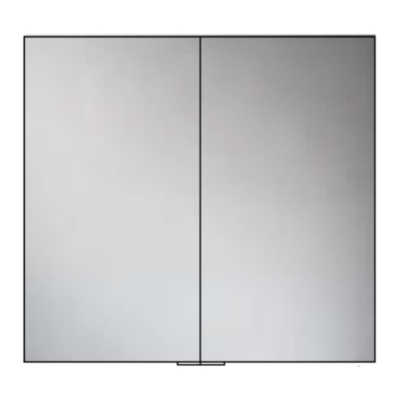
HiB 53200 Installation Instructions - Page 2
Browse online or download pdf Installation Instructions for Indoor Furnishing HiB 53200. HiB 53200 4 pages. Cabinet

PLEASE NOTE
This product can only be recessed fitted into a wall. A minium of 80mm depth is required. Before
installing ensure you take note of measurements for the area of the cabinet that will be recessed into the
wall and the side fixing points inside the cabinet carcass (See Fig. B & D).
DO NOT fit the shelves until the cabinet is installed and secured in place.
Fixing Preparation and Installation
Before installation, ensure the construction of
the wall is suitable to accommodate the size and
weight of a recessed cabinet.
The cabinet should be placed in a suitable
location, (according to the zonal diagram (Fig. 1)
on the back page).
Ensure the domestic electrical mains supply to
which the cabinet is being connected is turned
off.
NB. Cabinets must be installed with a minimum
distance of 150mm between the infra-red sensor
switch and any adjacent wall or object to ensure
correct operation of the sensor
1.
Measuring the back of the cabinet take note
of the external dimensions. This will be the
required wall aperture for the installation.
2.
Using these dimensions, take a soft pencil
and mark the outline for the required
aperture in the wall. Take great care to
mark this accurately, straight and level.
3.
Using an appropriate tool, cut or channel out
the aperture in the wall where the cabinet
will fit (Fig. A).
4.
If necessary, install supporting baton(s) or
noggin(s) around the recessed area (see
Fig. B) to which the cabinet can be secured.
These supports must be completely vertical
and parallel to the cabinet to prevent the
cabinet twisting when fitted.
5.
Ensure the thickness of the wall's final finished
surface allows the cabinet to be attached to
the internal support structure of the wall.
6.
Remove cabinet from the aperture and apply
your final wall finish. (Tiling, shower board for
example)
7.
Connect the domestic mains supply
according to the wiring diagram (See Fig. F)
opposite and manoeuvre the cabinet into the
wall aperture (See Fig. C).
2
8.
Using a suitable screwdriver or drill, secure
the cabinet into the wall aperture, via two
holes with the supplied screws (two on
each side) See Fig. D.
9.
Adjust the shelf support brackets to your
desired height ensuring the matching
brackets are level. This is done by slightly
loosening the screw, do not remove the
screw completely. Once in position tighten
screw to secure bracket and put the glass
shelf into shelf support bracket (See Fig.E).
10. Switch mains supply back on.
Operation Instructions
To switch on/off
Slowly move your hand past the sensor.
To change the colour temperature
1.
To alter the colour temperature of the
cabinet, hold your hand underneath the
sensor, (external, bottom right) the colour
temperature will start to change.
2.
Simply move your hand away from the
sensor when the desired colour temperature
has been reached and continue to operate
the cabinet as normal - the chosen colour
temperature will remain even after power is
switched off and on again.
