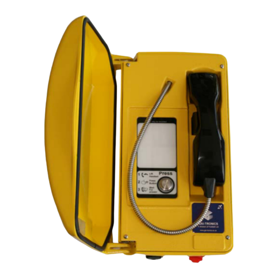
GAI-Tronics ILC-1117 Installation And User Manual - Page 9
Browse online or download pdf Installation And User Manual for Telephone GAI-Tronics ILC-1117. GAI-Tronics ILC-1117 20 pages. Titan illuminated crossing telephone

Kit No 100-02-0208-001
This accessory is for mounting GAI-Tronics telephones on to the side of
round poles of 100mm to 200mm diameter, or on to square or
rectangular section uprights of 100mm to 150mm across the mounting
surface.
NOTE:
Banding straps (large scale worm-drive clamps) are not included in this
kit and must be obtained separately. For details of where banding can
be obtained, refer to GAI-Tronics.
1. Using a suitable tool, punch out the 4 outer holes in the rear
enclosure, taking care not to damage or dislodge the plastic
bushes.
2. Attach the pole mounting clamp assemblies to the rear enclosure
using the M6 x 25 screws provided, pushing the screws through
from inside the phone.
3. Tighten nuts to a torque of 4.5Nm max.
IMPORTANT: avoid the use of power tools. Spinning the nuts too
quickly can cause a rapid increase in heat which can cause the nuts
to seize as a result of galling or cold-welding.
Note: only use the outer four holes, and ensure that the screws seat
properly in the plastic bushes to avoid water ingress.
4. Ensuring that the glands are at the bottom, pass a proprietary
banding strap round each of the pole mounting clamps and the
support pole. Tighten securely.
5. Continue the installation by making the appropriate connections
(section 5) and re-fitting the face plate.
6. Re-tighten the straps firmly and trim off any excess band material.
For security the driving head of the band may also be sawn off.
5.
Connections and option settings
If glands are used, insert the cable through the gland body and tighten the gland nut
sufficiently to clamp the cable, making a seal. Ensure sufficient cable is left to allow
removal of the faceplate without straining the cable.
ILC-1117 Titan Illuminated Crossing Telephone
9
