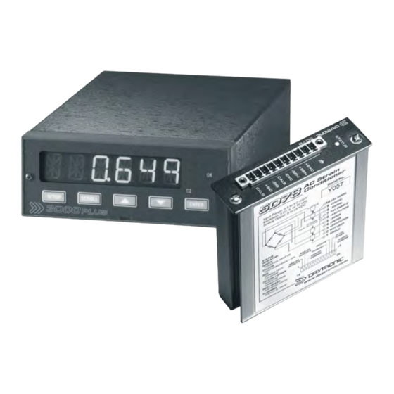
DayTronic 3000PLUS Instruction Manual - Page 20
Browse online or download pdf Instruction Manual for Measuring Instruments DayTronic 3000PLUS. DayTronic 3000PLUS 20 pages. Panel meter, frequency conditioner module
Also for DayTronic 3000PLUS: Instruction Manual (20 pages)

2.
T
D
RANSDUCER
Each wire or jumper of the transducer cable is to be
firmly secured to the appropriate screw terminal of the
terminal block that plugs into the 5D40(V)'s 10-pin
TRANSDUCER CONNECTOR.
As shown in Figs. 8.a and 8.b, below, the Model
5D40(V)'s differential inputs (+SIGNAL and –SIGNAL)
are normally used when connecting the module to a
magnetic pickup for conventional tachometric applica-
tions. When the ±SIGNAL lines are used for direct sen-
sor connections, note that
• The TTL SIGNAL input (Terminal 7) must be tied to
–EXCITATION (Terminal 6).
• It is strongly recommended that the –SIGNAL line
be tied to the module's 0.1 µF COUPLING terminal
(as shown in Figs. 8.a and 8.b). This serves to sup-
press unwanted signal noise, especially at the low-
frequency input range.*
Fig. 8.a gives the wiring for a pickup connection via
shielded twisted-pair cable, while Fig. 8.b gives the
wiring for a pickup connection via coaxial cable. With
coaxial cabling, the shield connection is not required,
and the –SIGNAL line should be tied to EXCITATION
COMMON (Terminal 10), which then connects directly
to the sensor (as shown).
The Model 5D40(V)'s TTL input should be used when
connecting the module to any generic TTL device (Fig.
Fig. 8
Model 5D40
Transducer Connections
Fig. 8.a
Input from Magnetic
Pickup, Using
Twisted-Pair Cable
3KPLUS with 5D40 I NSTRUCTION M ANUAL V . SB.3
C
ONNECTIONS
8.c) or to a "zero-velocity" (true digital output) sensor
requiring 5-V excitation (Fig. 8.d). When the TTL SIG-
NAL is directly connected to the sensor, the +SIGNAL
and –SIGNAL inputs must be tied to EXCITATION COM-
MON (Terminal 10) and –EXCITATION (Terminal 6),
respectively.
ALSO NOTE: The general TTL connections shown in
Fig. 8.c should always be used when the input frequen-
cy is greater than 200 KHz or less than 2 Hz.
An additional wire is shown in Fig. 8.d connecting the
zero-velocity sensor's –EXCITATION pin and the
5D40(V)'s EXCITATION COMMON (Terminal 10). This
wire is recommended when the cable resistance is
greater than 20 ohms. When used, the additional wire
and the +EXCITATION line should make a separate
shielded twisted pair, as shown. The +SIGNAL and
main –EXCITATION lines should always be paired and
shielded.
For general information on CABLE SHIELDING, see
Section 2.B.
* The larger 10 µF COUPLING (Terminal 4) is for removal of rela-
tively large amounts of ± DC offset, and is not normally
required. Contact the factory for connection details.
SHIELDED TWISTED PAIR
MAGNETIC
PICKUP
* (NOT ISOLATED; connects
2. C
ONNECTIONS
SCREW TERMINAL BLOCK
PLUGGED INTO TRANSDUCER
CONNECTOR
internally to CHASSIS GROUND)
5D40
10
EXC. COMMON
9
+SIGNAL
8
–SIGNAL
7
TTL SIGNAL
6
–EXCITATION
5
0.10 µF COUPLING
4
10 µF COUPLING
3
+EXCITATION
2
[FOR FUTURE USE]
1
SHIELD*
3KP40 - 2.3
