HID Corporation ThinLine II 5395B Installation Manual - Page 2
Browse online or download pdf Installation Manual for Card Reader HID Corporation ThinLine II 5395B. HID Corporation ThinLine II 5395B 5 pages.
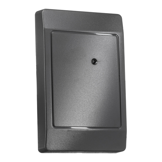
ThinLine II Reader Installation Manual - System Overview
The ThinLine II Reader is a self contained proximity Reader frequently used in Access Control Systems.
The antenna and all associated electronics are assembled in a polycarbonate housing. The Reader
contains a micro-controller unit that controls an RF field that is generated at 125kHz. The Reader has a
sensitive receiver circuit that detects ID card data and passes it along to the micro-controller for
decoding. The Reader output is configured in the "Wiegand" style electrical interface. The Reader has a
single Bicolor LED that will emit red, green or amber colors. Installation of the ThinLine II Reader
consists of mounting the Reader and connecting the cable to the Host via the Pigtail cable.
Operation
Access Cards are to be presented to the front of the Reader. The LED is red when ready to read an ID
card. The LED turns green when the card is read and a message is transmitted to the Host computer or
interface panel. When the system is ready for another card, the LED returns to red. The is LED is
flashed green and the Beeper is activated for 250 milliseconds when they are controlled by the internal
micro-controller. The operation of the LED and beeper is often controlled by the Host panel. If Host
controlled, the operation will deviate from Host to Host. The ThinLine II may be configured in the dual
LED control line that allows individual control of both the red and green colors of the LED.
Parts List
1) ThinLine II
2) #6-32 x 1" self tapping, Type T or 23
3) This Installation Sheet
4) Wire Splice
5) Grommet
6) DC Power Supply - +4.75 to 16VDC, 50mA
7) Cable, 5 conductor , 22 AWG
Installation Procedure
1.
Determine an appropriate mounting position for the Reader. Drill two 7/64th (.109) Inch holes for
mounting the Reader to the surface. Drill a 3/8 to 1.0 Inch hole for the cable. If mounted on metal,
place a grommet around the edge of the hole. Route the interface cable from the Reader and/or
power supply to the Host. Check all electrical codes for proper cable installation.
2.
The ThinLine II is available with either a 15" Pigtail or a 2 meter Pigtail, as shown in the
configurable options/ordering information, below. To make the cable connection, prepare the new
cable by cutting the cable jacket back 1-1/4" and strip the wires ¼". Splice the cable and the pigtail
together and seal the splice if the ThinLine II will be an outdoor unit. Trim and cover all conductors
that are not used.
3.
Connect the Reader and Host together according to the wiring diagram (below) and the Host
installation guide. The legend for wiring is color coded (according to the "Wiegand Standard") for
the recommended cable, but marking the wires will make future maintenance easier. The color of
the legend on the back label is the color of the respective wire.
4.
After wiring the Reader and power supply, the Reader is ready to be tested. Power up the Reader
and the LED and Beeper will flash and beep 3 times in a sequence of two short delays and one
long delay. This indicates that the micro-controller unit is working properly. Present an ID card to
the Reader and the LED should momentarily turn green, indicating a read of the card. If the
Reader LED is controlled by the Host refer to the Host description of the LED operation.
5.
Mount the Reader with the provided screws when mounting onto spacers or junction boxes. On
other materials use the appropriate fastener.
____________________________________________________________________________________________
HID Corporation 9292 Jeronimo Road Irvine, CA 92618-1905 USA TEL (949) 598-1600 (800) 237-7769 FAX (949) 598-1690 Web
page, E-mail - www.prox.com ThinLine II Reader Installation Manual 5395-901 REV B
Проектирование. Монтаж. Продажа. - http://vskd.ru
Quantity
1 (included)
2 (included)
1 (included)
9 (installer supplied)
1 Recommended (installer supplied)
1 (installer supplied)
Up to 500ft. (installer supplied) Alpha 1295C
2 of 5