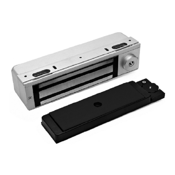
DynaLock 3101B-TJ101 Mounting Instructions - Page 2
Browse online or download pdf Mounting Instructions for Locks DynaLock 3101B-TJ101. DynaLock 3101B-TJ101 4 pages. Electromagnetic lock
Also for DynaLock 3101B-TJ101: Wiring Instructions (13 pages)

705 Emmett Street Bristol, CT 06010
1-877-DynaLock www.dynalock.com
MOUNTING CONSIDERATIONS
1.
Individual door and frame
conditions may vary. Dimensions
shown at right are for a typical
hollow metal door and frame.
2.
The lock assembly should be
mounted closest to the strike
jamb of the frame for maximum
performance. Verify that there
is proper clearance for the
lock assembly at the planned
mounting location.
SEX NUT
INSTALL THE LOCK ASSEMBLY
1.
Drill out the four dimpled mounting hole locations inside the
back of the lock housing using a 5/32" drill. Position the lock
assembly on the face of the frame header, on the pull side of
the door, as shown. Locate and mark the centers of the four
mounting holes.
2.
Drill the marked holes in the face of the frame header:
Four (4) 5/32" dia. mounting holes.
3.
Attach the lock assembly to the frame header using four (4)
#14-1½ pan head wood screws or 10/32 x 1¾ philips pan head
machine screws. Firmly tighten the screws using a #2 phillips
screwdriver.
MOUNTING HOLES
FLUSH WITH
FRAME RABBETT
LEFT HAND DOOR
1/8"
ABOVE
HEADER RABBETT
HINGE SIDE
3101B-TJ101 INSTALLATION MANUAL
MODEL 3101B-TJ101
ELECTROMAGNETIC LOCK
MOUNTING INSTRUCTIONS
4-7/16"
1/4"
TYP.
ARMATURE
LOCK ASSEMBLY
1/8"
1/8"
1/4"
GAP
GAP
REF.
2-3/4"
REF.
1-1/4"
ARMATURE BRACKET
MOUNTING SCREW
DOOR
MOUNTING HOLES
RIGHT HAND DOOR
1/8"
ABOVE
HEADER RABBETT
HINGE SIDE
Page 2
705 Emmett Street Bristol, CT 06010
1-877-DynaLock www.dynalock.com
5-1/8"
REF.
25
FLUSH WITH
FRAME RABBETT
Note: Refer to Page 6 for parts legend.
02/11
3101B-TJ101 INSTALLATION MANUAL
MODEL 3101B-TJ101
ELECTROMAGNETIC LOCK
MOUNTING INSTRUCTIONS
EXPLODED PARTS VIEW
11
10
12
9
13
14
23
15
16
17
22
18
19
21
26
Page 7
8
7
6
4
2
5
1
3
20
02/11
