Dynamic DX2-GYRO Installation Manual Addendum - Page 8
Browse online or download pdf Installation Manual Addendum for Control Unit Dynamic DX2-GYRO. Dynamic DX2-GYRO 20 pages. The ultimate powerchair control solution

2.3 The DX2-GYRO Module
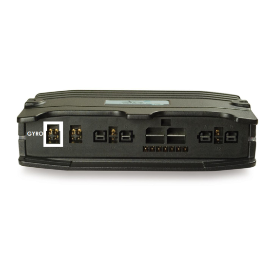
The cable length is 600 mm. For connector information see section 3.2.
: Issue 2.03 - May 2012
GBK65248
8
Ensure that the DX2-Gyro module is mounted in a true vertical axis
(exactly 90 degrees to the horizontal ground level). Two mounting
holes are required: one for the M6 mounting bolt, the second for the
orientation spigot.
The orientation spigot, located towards the top of the module (see
diagrams below), ensures that the Gyro module cannot rotate out of
position once it has been secured to the wheelchair frame.
Front view
Side view
Note:
Mount the DX2-GYRO module so that the cable is located on the top side of
the unit, with the cable rising vertically upwards. The module will not function
in any other position.
Warning:
Mount the Gyro module in a position where the user cannot touch it.
Orientation
spigot
Rear view
Orientation
spigot
Top view
