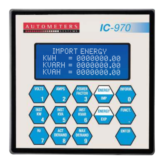
Autometers Systems IC 970 Installation & Operating Manual - Page 11
Browse online or download pdf Installation & Operating Manual for Measuring Instruments Autometers Systems IC 970. Autometers Systems IC 970 12 pages.

Transformer selection
Current Transformer Selection
For accurate monitoring, correct selection of current transformers are critical. The following
paragraphs provide the information required to choose these transformers.
The 900 range of meters use current transformers (C T ) to sense the current in each phase of the
power feed. The selection of the C Ts is impor tant because it directly affects accuracy.
The C T secondar y rating depends on the current input option installed. The standard IC 900
current rating is 5 amps.
The C T primar y rating is normally selected to be equal to the current rating of the power feed
protection device. However, if the peak anticipated load is much less than the rated system
capacity then improved accuracy and resolution can be obtained by selecting a lower rated C T.
In this case the C T size should be the maximum expected peak current +25%, rounded up to the
nearest standard C T size.
O ther factors may affect C T accuracy. The length of the C T cabling should be minimised.
Also the C T burden rating must exceed the combined burden of the IC 900, plus cabling,
together with any other connected devices.
Overall accuracy is dependent on the combined accuracies of the IC 900 ME TER and
the current transformers.
20
Performance and data
Measurements
The unit is designed for measuring 3 phase in a 4 wire star configuration.
Technical Parameters
Meter standard
BS EN 61036
Accuracy
Active 1.0, reactive 2.0
Reference Voltage
3 x 230/400 volt
Basic Current
5 amp
Maximum Current
6 amp
Frequency
50/60 Hz
Pulse Constant
5000 imp/kWh,
5000 imp/kVarh
Outputs
There are two optically isolated volt free relays on the IC 970.
Pulse duration: Programmable.
Pulse Value: Programmable.
Default 100 ms
Default 1 kWh, 1 kVah
Relay contacts maximum switching voltage 230 volt 100 Ma
Maximum switching current 0.75 Amp (switching power 30 va)
Communication Module
Fully programmable 485 Modbus Default.
Baud Rate:
9600
Wire Mode:
2 WIRE
Modbus Type:
RTU
Definitions
Measurement Category CATIII
Measurement categor y III is for measurements per formed in the building installation. Note 2
examples are measurements on distribution boards, circuit breakers, wiring, including cables,
bus-bars, junction boxes socket-outlets in the fixed installation, and equipment for industrial use
and some other equipment, for example, stationar y motors with permanent connection to the
fixed installation.
Double Insulation Symbol
Table 1 symbol 11, IEC 60417-5172
Defined as: Insulation comprising both basic insulation and supplementar y insulation.
Range of voltage
200v – 250 v
Operation temperature
- 10ºC + 50ºC
Storage temperature
- 10ºC + 60ºC
Humidity
<=95%
Power consumption
0.01VA @5A; 1.5W
10VA @230 volt
Pulse output
BS EN 62053 -31
Parity Type:
EVEN
Data Format:
FLOATING POINT
FP. Format:
HIGH WORD 1st
!
Caution, risk of electric shock
21
