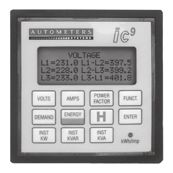
Autometers Systems ic9 Installation And Operation Manual - Page 3
Browse online or download pdf Installation And Operation Manual for Measuring Instruments Autometers Systems ic9. Autometers Systems ic9 9 pages.

Wiring information
Power supply
The standard IC9 requires a 230
volt 50 Hz supply. This is powered
from the L3 phase and Neutral
internally.
Wiring
Electrical and communication
connections are made directly to
the back of the meter.
The main electrical connections are
made to terminals 1-16 at the lower
half of the meter, Communication
Modbus 485 connections are made
via the two sockets at the top of the
meter on the side. Please see dia 2.
Programming
the CT Ratio '13'
To programme the CT Ratio the
dill switch number "8" on the
lower dill switch block must be in
the "On" position
See diagram 6 for position of dill
switches.
Connect power to the meter.
To programme, press the
function key on the front of the
meter, which will then take you
into the display sequences for
programming the CT Ratios.
You should now see the screen
below
PLEASE ENTER
FUNCT I ON NUMBER
**
Diagram 3: Programming Screen
(a) You will notice the cursor
flashing on the first "zero", by
pressing the "Energy" key the
zero will change to 1, if you
the "Energy" key again it will
change to 2 and so on.
(b) If you go past your number
continue going through the
numbers until the number you
require reappears. Stop at your
correct number '1'.
(c) Press the "Enter" key and the
flashing cursor will move to the
right. Stop at number '3'. Press
function.
Diagram 4 : CT Setting Screens
RAT I O
CT PR I MARY=**** / 5
NT PR I MARY=**** / 5
(d) Repeat steps (a) to (c) to enter
the correct programming details
for your chosen CT ratios.
(e) When the process is complete
press the "Function" key to take
you back to the default screen.
Note: When setting CT ratios and
if you have only three digits you
must enter "0" as the first digit.
e.g. 100/5 would be entered as
0100/5.
When you have programmed the
meter, disconnect the power to
the meter and ensure dill switches
are set to the 'OFF' position.
Operating
information
Power on
After you have programmed the
meter and you have put power
onto the meter, the first screen
to appear will indicate details of
the meter and your programmed
parameter values. After 10
seconds will revert to normal
press
default screen. "b"
a) Power On:
3P4W 230 / 400V 50HZ
b) Normal Default Display
KWH
KVAH
KVARH = 000000.00
Test Mode Display
At this stage it is advisable to check
the connection to the meter, to do
this please see page 6 function 50.
This will enable you to see if the
current transformers have been
connected correctly and the three
voltages are present.
Diagram 5: Connection Check Screen
L 1 i mpo r t
L2 i mpo r t
L3 i mpo r t
The diagram above is showing
that the current transformers
are correct and the three phase
voltages are correct.
If the current transformers are
correct but the voltage on each
phase is missing or below 200
volts, then the screen will look as
in the diagram below:
L 1 i mpo r t
L2 i mpo r t
L3 i mpo r t
3
9
I C
CT Rat i o
****:5
NT Rat i o
****:5
I MPORT ENERGY
= 000000.00
= 000000.00
CONNECT I ON
V 1 ON
V2 ON
V3 ON
CONNECT I ON
V 1 OFF
V2 OFF
V3 OFF
