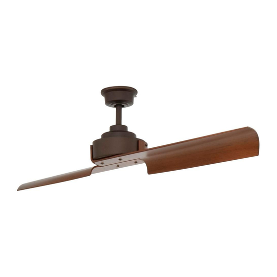
Aire Magnitude 34348 Instruction Manual Warranty Certificate - Page 8
Browse online or download pdf Instruction Manual Warranty Certificate for Fan Aire Magnitude 34348. Aire Magnitude 34348 17 pages.

HANGING THE FAN-STANDARD CEILING MOUNTING
WARNING: All of the parts, hardware and components such as the hanger bracket and hanger ball have been provided
for your safety and the proper installation of your new ceiling fan. The use of other parts, hardware or components not
supplied by Aire with the fan will void the Aire Warranty.
REMEMBER to turn off the power. Follow the steps below to hang your fan properly:
Step 1. Remove the canopy ring from the canopy by turning the canopy ring counterclockwise. Remove the mounting
bracket from the canopy by loosening the four screws on the top of the canopy. Remove the two non-slotted screws and
loosen the slotted screws. (Figure 7)
Step 2. Pass the 120-volt supply wires through the center hole in the mounting bracket. Attach the mounting bracket on
the outlet box by sliding the mounting bracket over the screws provided with the outlet box. When using
"close-to-ceiling" mounting, it is important that the mounting bracket be level. If necessary, use leveling washers (not
included) between the mounting bracket and the outlet box. Note that the flat side of the mounting bracket is toward
the outlet box. (Fig. 8)
Step 3. Loosen the two Set Screws and remove the Hitch Pin and Lock Pin from the coupling located on the top of the
Motor Assembly. (Fig. 9)
Step 4. Remove the Hanger Ball from the Downrod Assembly by loosening the Set Screw and removing the Cross Pin.
Remove the ground lead from the downrod.
Step 5. Carefully feed fan wires up through the downrod. Thread Downrod into the Coupling until the holes are lined up
and secure with the Lock Pin and Hitch Pin previously removed, tighten Set Screws. (Fig. 11)
Step 6. Slip coupling cover, canopy cover, canopy ring and canopy onto downrod. Carefully reinstall hanger ball onto rod
and reinstall the ground lead onto the downrod, being sure that cross pin is in correct position, set screws are tighten
and wires are not twisted. (Fig. 12)
Step 7. Lift the Motor Assembly and place the Hanger Ball into the Hanger Bracket. Rotate the Motor Assembly as needed
until the check groove from the Hanger Ball rests firmly over the registration tab from the Hanger Bracket. (Fig. 13)
LOOSEN
BUT DO NOT
REMOVE
REMOVE
CANOPY RING
CANOPY
FIG. 7
DOWNROD
SUPPLY
WIRES
FIG. 11
(Fig. 10)
OUTLET BOX
HANGER BRACKET
FIG. 8
CROSS PIN
SET SCREW
DOWNROD
COUPLING
COVER
LOCK PIN
FIG. 12
SET SCREWS
HITCH
LOCK
PIN
PIN
FIG. 9
GROUND
LEAD
HANGER
BALL
CANOPY
CANOPY RING
CANOPY COVER
SET SCREWS
HITCH PIN
8
CROSS PIN
HANGER
BALL
SET
SCREW
GROUND
LEAD
DOWNROD
FIG. 10
REGISTRATION
SLOT
FIG. 13
