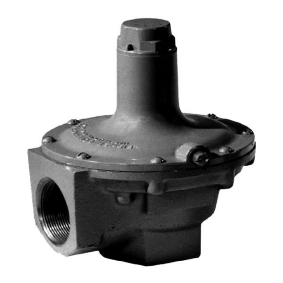
Emerson 289 Series Instruction Manual - Page 2
Browse online or download pdf Instruction Manual for Control Unit Emerson 289 Series. Emerson 289 Series 11 pages.

289 Series
Specifications
This section lists the specifications for the 289 Series regulators. Factory specification are stamped on
the nameplate fastened on the regulator at the factory.
Available Configurations
See Table 1
Body Sizes and Inlet Connections
Type 289L: 3/4 or 1 NPT Types
289A and 289U: 1/4 NPT Type
289H: 1 or 2 NPT
Type 289HH: 1 NPT
Maximum Allowable Relief (Inlet) Pressure
Maximum Relief Set Pressure
See Table 1
Material Temperature Capabilities
Nitrile (NBR) and Neoprene (CR):
-20 to 150° F / -29 to 66° C
Fluorocarbon (FKM)
(2)
20 to 300° F / -7 to 149° C
Available with Types 289H and 289HH only
1. The pressure/temperature limits in this Instruction Manual and any applicable standard limitation should not be exceeded.
2. Bubble-tight shutoff cannot be attained at settings below 5 psig / 0.34 bar with Fluorocarbon (FKM) O-ring seat.
Principle of Operation
Refer to Figures 2 and 4. The 289 Series Relief
valves are to be installed (between large service
regulators such as S202G or S302G Series) so the
outlet is piped downstream to relieve excess pressure
to the atmosphere. As inlet pressure increases, the
spring is compressed by the diaphragm, moving the
disk away from the seat. When the valve is opening,
high gas velocity through the orifice creates an area
of relatively low pressure near the end of the pitot
tube. This pitot tube effect forms a partial vacuum
above the diaphragm (spring case area) which helps
to open the valve further.
Installation
Warning
!
Installing a 289 Series relief valve where
its capabilities can be exceeded or where
proper operation might be impaired may
cause personal injury, property damage
or leakage due to bursting of pressure-
containing parts or explosion of
accumulated gas. To avoid such
2
บริ ษ ั ท เอดี ด ี เฟอร์ เ นส จ ำกั ด
ADD FURNACE CO.,LTD.
44 ซอยบรมราชชนนี 70 ถนนบรมรำชชนนี แขวงศำลำธรรมสพน์ เขตทวี ว ั ฒ นำ กรุ ง เทพฯ 10170
โทร: 02-888-3472 โทร: ออกแบบ
https://www.add-furnace.com E-mail:
and
(1)
(1)
:
แฟกซ์ : 02-888-3258
08-08-170-170
:
Pressure Setting Adjustment
Adjusting screw
Pressure Registration
Internal
Approximate Shipping Weights
Types 289A and 289U: 0.75 lbs / 0.3 kg
Type 289H:
1 NPT Size: 4 lbs / 2.0 kg
2 NPT Size: 15 lbs / 7.0 kg
Type 289HH: 4 lbs / 2.0 kg
Type 289L: 15 lbs / 7.0 kg
Additional Specifications
For construction materials, see Parts List.
conditions, install a 289 Series
relief valve where:
• Service conditions are within the
unit capabilities specified in the
Specifications section and
• The relief valve is protected from
exposure to physical damage and/or
corrosive substances.
1. When installing a 289 Series relief valve, make sure
that the installation of the system complies with
applicable local, state or federal codes or regulations.
2. Use qualified personnel when installing, operating
and maintaining a 289 Series relief valve. Before
installation, make sure there is no damage to
or foreign material in the relief valve and that
all piping is clean and unobstructed.
3. For installation of Types 289H, 289HH and
289L relief valves, the vent in the spring case
must remain plugged or undrilled in order for
the pitot tube to function properly.
4. The 289 Series relief valves may be installed in any
orientation. However, when installing the relief valve at
an outside location, adequate protection, such as rain
caps or elbow piping (see Figure 4), must be attached
to the outlet to keep the relief valve from getting
plugged or from collecting moisture, corrosive
