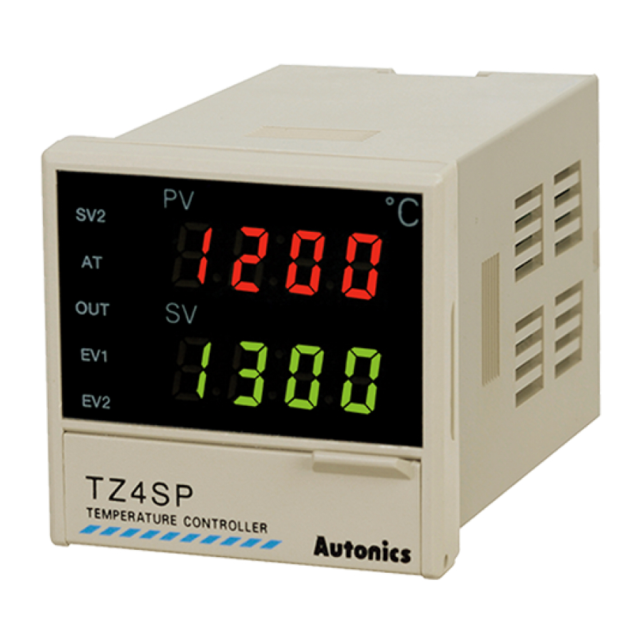
Autonics TZN4M Manual - Page 13
Browse online or download pdf Manual for Controller Autonics TZN4M. Autonics TZN4M 17 pages. Dual pid control temperature controller
Also for Autonics TZN4M: Manual (4 pages), Instruction Manual (2 pages), Manual (16 pages), Manual (16 pages), Manual (17 pages)

TZN/TZ Series
Alarm (event)
Alarm output can be configured by combining alarm operation and alarm options. Set the alarm operation in event 1/2 [EU1,
EU2] of parameter group 2, and set the alarm options in alarm option [AL-T].
1) Alarm operation
Mode
Name
Alarm operation
-
-
AL-0
Deviation
AL-1
high-limit
alarm
Deviation
low-limit
AL-2
alarm
Deviation
high-limit
AL-3
/low-limit
alarm
Deviation
high-limit
AL-4
/low-limit
reverse
alarm
Absolute
value
AL-5
high-limit
alarm
Absolute
value
AL-6
low-limit
alarm
-
SBA
Sensor break
-
LBA
Loop break
※ H: Alarm output hysteresis[ AHYS ]
2) Alarm options
Mode
Name
Description
AL-A Standard alarm Alarm output turns ON upon alarm condition, and alarm output turns OFF when condition is cleared.
AL-B Alarm latch
Alarm output turns ON and maintains ON upon alarm condition.
The first alarm condition is ignored. It will operate as standard alarm from the second alarm condition. If it is under
Standby
alarm condition when power is supplied, it will ignore the condition and operate as standard alarm from the next
AL-C
sequence
alarm condition.
Alarm latch
It will operate as both alarm latch and standby sequence upon alarm condition. If it is under alarm condition when
and standby
AL-D
power is supplied, it will ignore the condition and operate as alarm latch from the next alarm condition.
sequence
3) Sensor break alarm
Alarm output turns ON when sensor is not connected or loses its connection during temperature control. Sensor
disconnection can be tested by connecting buzzers or other devices to the alarm output contact. Sensor break alarm output
operates through EV1 OUT or EV2 OUT contacts. Alarm output is disengaged after resetting the power.
4) Loop break Alarm (LBA)
Diagnose control loop and transmit alarm output through temperature change of control target. During heating(cooling)
control, the alarm output turns ON if the PV does not rise/drop by a specific amount (approx. 2℃) during LBA monitoring
period [LBA] while control output amount is at 100%(0%).
※ If the thermal response of the control target is slow, the LBA monitoring period [LBA] of parameter group 1 should be set
longer.
※ LBA only operates when the control output amount is 100%(0%) so it cannot be used in current output models.
※ If the alarm output turns ON after the sensor has been disconnected, the alarm output will not turn OFF even after
reconnecting the sensor. To disengage the alarm output, the temperature controller power must be reset.
J-152
OFF
SV
100℃
High-limit deviation: 10℃
ON
H
PV
90℃
Low-limit deviation: 10℃
ON
H
OFF
PV
SV
90℃
100℃
High-limit/low-limit deviation: 10℃
OFF
H
ON
PV
SV
100℃
90℃
High-limit/low-limit deviation: 10℃
OFF
H
ON
PV
SV
90℃
100℃
Absolute value alarm: 90℃
ON
H
OFF
PV
SV
90℃
100℃
Absolute value alarm: 90℃
H
ON
PV
110℃
OFF
SV
100℃
H
ON
PV
110℃
H
OFF
PV
110℃
OFF
H
ON
SV
PV
100℃
110℃
Absolute value alarm: 110℃
ON
H
OFF
SV
PV
100℃
110℃
Absolute value alarm: 110℃
Description
Alarm output not used.
If the deviation of PV and SV are higher than
the high-limit deviation, the alarm output turns
ON.
If the deviation of PV and SV are higher than
the low-limit deviation, the alarm output turns
ON.
If the deviation of PV and SV are higher than
the high-limit deviation or low-limit deviation, the
alarm output turns ON.
If the deviation of PV and SV are higher than
the high-limit deviation or low-limit deviation, the
alarm output turns OFF.
Alarm output turns ON when PV is higher than
the absolute value.
Alarm output turns ON when PV is lower than
the absolute value.
Alarm output turns ON when sensor
disconnection is detected.
Alarm output turns ON when loop break is
detected.
