dbx 263A Operation Manual - Page 6
Browse online or download pdf Operation Manual for Recording Equipment dbx 263A. dbx 263A 8 pages. De-esser

MODEL 263A
FROM SOURCE DEVICE
TO NEXT DEVICE
SLEEVE
1
2
TIP
3
RING
XLR-TYPE FEMALE
FEMALE XLR-TYPE TO STEREO PHONE PLUG
FROM SOURCE DEVICE
TO NEXT DEVICE
SLEEVE
SLEEVE
TIP
TIP
RING
RING
STEREO PHONE PLUG TO STEREO PHONE PLUG
FROM SOURCE DEVICE
TO NEXT DEVICE
1
2
SLEEVE (-)
3
TIP (+)
XLR-TYPE MALE
MONO PHONE PLUG TO MALE XLR-TYPE
FROM SOURCE DEVICE
TO NEXT DEVICE
SLEEVE (-)
1
1
2
2
3
3
TIP (+)
XLR-TYPE MALE
RCA PHONO PLUG TO MALE XLR-TYPE
FROM SOURCE DEVICE
TO NEXT DEVICE
SLEEVE (-)
SLEEVE (-)
TIP (+)
TIP (+)
MONO PHONE PLUG TO MONO PHONE PLUG
FROM SOURCE DEVICE
TO NEXT DEVICE
SLEEVE
SLEEVE (-)
TIP
TIP (+)
RING
STEREO PHONE PLUG TO MONO PHONE PLUG
FROM SOURCE DEVICE
TO NEXT DEVICE
SLEEVE
SLEEVE (-)
TIP
TIP (+)
RING
PHONO PLUG TO MALE XLR-TYPE
OPERATION MANUAL
FROM SOURCE DEVICE
TO NEXT DEVICE
SLEEVE
1
2
3
TIP
RING
XLR-TYPE MALE
STEREO PHONE PLUG TO MALE XLR-TYPE
FROM SOURCE DEVICE
TO NEXT DEVICE
2
1
1
2
3
3
XLR-TYPE FEMALE
XLR-TYPE MALE
FEMALE XLR-TYPE TO MALE XLR-TYPE
FROM SOURCE DEVICE
TO NEXT DEVICE
SLEEVE (-)
SLEEVE
TIP (+)
TIP
RING
MONO PHONE PLUG TO STEREO PHONE PLUG
FROM SOURCE DEVICE
TO NEXT DEVICE
SLEEVE (-)
SLEEVE
TIP
TIP (+)
RING
PHONO PLUG TO STEREO PHONE PLUG
FROM SOURCE DEVICE
TO NEXT DEVICE
SLEEVE (-)
SLEEVE (-)
TIP (+)
TIP (+)
PHONO PLUG TO MONO PHONE PLUG
FROM SOURCE DEVICE
TO NEXT DEVICE
SLEEVE (-)
SLEEVE (-)
TIP (+)
TIP (+)
MONO PHONE PLUG TO PHONO PLUG
OPERATION MANUAL
Input/Output Connections
ABOUT DE-ESING WITH THE 263A
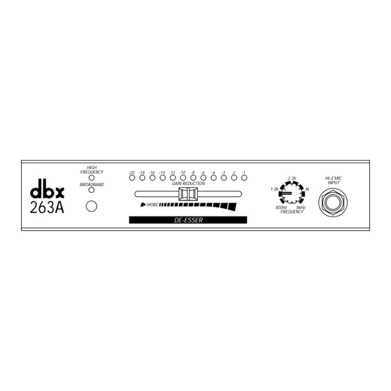
High Frequency or Broadband?
In order to detect that harsh, spitty sound of excess sibilance, all incoming signals are split into two fre-
quency bands regardless of this button setting. Too much ÒessÓ content shows up as too much high fre-
quencies relative to lows; the 263A circuit responds whenever this happens. The button controls what
happens to the signal you hear at the 263A output when the detector circuit recognizes an Òess.Ó
If the button is set to the HF position, the circuit reduces the high-frequency band only -- which (as noted)
is generally the best choice for live situations and recording. This brings down only the frequencies
where excessive ÒessÓ are located.
The Broadband setting helps more during mixdown, for excess sibilance tends to saturate tape, produc-
ing low-frequency modulation products -- distortion -- during playback. In this setting the entire frequency
spectrum gets attenuated, which reduces the level of the distortion along with the sibilance.
The slider
This governs the overall amount of processing. With most material, mid-settings will work well; these
reduce the ÒessÓ just enough to put the balances aright. Vary them to suit your ear. Also experiment with
wider departures from the middle for non-vocal material, but be advised that far-right settings may cause
sibilants to sound swallowed, even comical.
The Frequency knob
This sets the crossover point between the high and low bands (again, 4kHz is a good starting point).
Subtle variations can be achieved with fine-tuning and a close ear on the characteristics of the vocal.
Note that this knob varies the crossover point for the detector even when youÕre in the Broadband setting.
The technically minded will want to know that the 263A band-splitting filters are phase-coherent, ensuring
accurate phase relationships at the output after the signals are recombined.
Some Elementary Phonetics
Sibilance is the hissing or rushing sound produced by blowing air thru a constricted (narrowed) mouth
opening or across the edge of the teeth, as in the ÒsÓ and ÒsshÓ in Òsash.Ó Sibilants contain predominantly
high-frequency components with a sharp rise above 1kHz and most of the energy in the 4-10 kHz band,
centered on 6-8 kHz. Much of the energy in non-sibilant speech (vowels and semi-vowels) for both
sexes lies in the 200-400 Hz octave with a rolloff above 1kHz. The singing voice has the same spectral
distribution but usually contains additional small energy peaks and often a larger peak between 2 and 3
kHz, which can be 5 to 10 dB louder than for the same non-singing voice.
Because of the way it detects excesses of high-frequency energy, the 263A is very effective for vocal
problems wider -ranging than sibilance. Many sharp high-frequency sounds cause difficulty in recording
and sound-reinforcement situations; those produced by blocking the air flow and then suddenly releasing
it (ÒfÓs, ÒthÓs, etc., in addition to the sibilants) will be successfully handled by the 263A. Fore example, the
ÒtÓ in ÒtopÓ has a substantial peak around 8kHz with little energy below 4kHz; this type of sound can be as
troublesome as any.
Current studio and performance equalization often boosts the lead vocal track in the 4-8 kHz region, for
doing so improves intelligibility and crispness and makes the vocal cut through the hot mixes typical of
rock productions. This is fine until problem passages occur: the boost can cause an increase to the point
where (in extreme cases) one has trouble distinguishing between sibilance and cymbal crashes.
Compression on vocal tracks also commonly aggravates sibilance, for time constants that otherwise
sound smooth on vocals are often too slow to catch the elusive Òess.Ó Further, the energy contained in
¨
PROFESSIONAL PRODUCTS
