Autonics TM2-22RB User Manual - Page 5
Browse online or download pdf User Manual for Temperature Controller Autonics TM2-22RB. Autonics TM2-22RB 9 pages. Tm series

TM Series
DIN Rail Installation
[Installation method]
① ●Put●the●top●edge●of●the●rail●Lock●
on●the●top●edge●or●the●DIN●rail.●
② ●Push●the●module●body●in●while●
pressing●down.
Using●END●PLATE(Sold●separately,●Not
available●from●Autonics),●Fix●firmly●to●attach
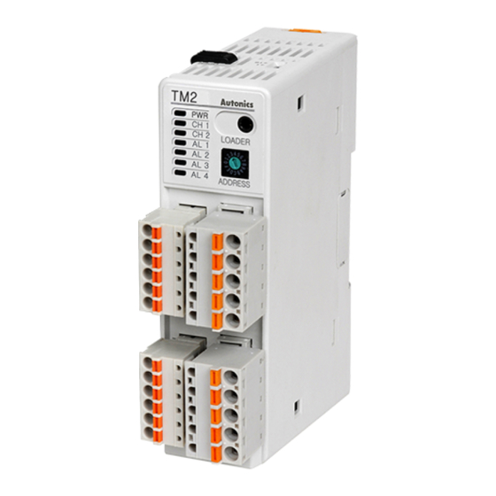
Parts description
TM2 Series
7
6
6
1
2
3
4
8
9
1. Display LED(TM2 Series)
●●●●●●●●●●●●●●●●●●Status
Initial●power●on
Display●LED
※ 3
PWR●LED
Green
CH1●LED
2400bps-Flashing
CH2●LED
4800bps-Flashing
AL1●LED
9600bps-Flashing
AL2●LED
19200bps-Flashing
AL3●LED
38400bps-Flashing
AL4●LED
-
2. Display LED(TM4 Series)
●●●●●●●●●●●●●●●●●●Status
Initial●power●on
Display●LED
※ 3
PWR●LED
Green
CH1●LED
2400bps-Flashing
CH2●LED
4800bps-Flashing
CH3●LED
9600bps-Flashing
CH4●LED
19200bps-Flashing
38400bps-Flashing
H-14
①
②
3. PC loader port(Port A)
TM4 Series
Integrated●device●management●program●(DAQMaster,●free●download●
on●our●site)●is●for●setting●parameter●by●PC●through●USB●to●Serial●
converter●(SCM-US,●sold●separately).
7
4. Communication address setting switch(SW1)
5
Used●to●set●communication●address.
5. Communication address group change switch(SW2)
3
When●communication●address●is●over●16,select●+16.
4
Ex)● F or●setting●20●address,●set●the●communication●address●group●
8
6. Lock switch
Used●for●fixing●units●to●DIN●rail●or●to●the●wall
7. Rail Lock
Used●for●fixing●each●module●when●connecting●module●units.●(up/down●side)
9
8. END Cover:●Remove●it●when●connecting●each●module.
9. Power supply / communications connector(PortB)
Only●Basic●module●TM - 2 B
※ 1
Control●output
Green
ON-RED
ON-RED
※ 4
ON-Yellow
※ 5
ON-Yellow
-
-
※ 1
Control●output
Green
ON-RED
ON-RED
ON-RED
ON-RED
-
[Removal method]
① ●Press●down●the●module●body.●
② ●Pull●the●module●body●forward.
※ Make sure to install the unit vertically to the ground.
Vertical●Installation
( O )
change●switch●(SW)●as●+16●and●set●the●commuicaiton●address●
setting●switch●(SW1)●as●4.
Alarm●output
N.O.●Alarm●occurred
OFF(OPEN)
ON(CLOSE)
-
-
-
-
-
-
Light●OFF
Light●ON
Light●OFF
Light●ON
Light●OFF
Light●ON
Light●OFF
Light●ON
※ 1:●In●case●of●initial●power●on,●default●communication●speed●
will●be●flashing●for●5●sec.●(1●sec.●cycle).
※ 2
Auto●tuning
※ 2:●Each●CH3●LED●will●be●flashing●during●auto●tuning●(1●sec.●
cycle).
Green
※ 3:●Power●LED●will●be●flashing●while●communicating●with●
Flashing
external●units●(1●sec.●cycle).
Flashing
※ 4:●Light●ON●when●control●type●for●CH1●is●heating●&●cooling●
Flashing
type●and●cooling●output●is●provided.
Flashing
※ 5.●Light●ON●when●control●type●for●CH2●is●heating●&●cooling●
type●and●cooling●output●is●provided.
-
①
②
Horizontal●Installation
( X )
N.C.●Alarm●occurred
OFF(CLOSE) ON(OPEN)
-
-
-
-
-
-
Light●OFF
Light●ON
Light●OFF
Light●ON
Light●OFF
Light●ON
Light●OFF
Light●ON
※ 2
Auto●tuning
Green
Flashing
Flashing
Light●OFF
Light●OFF
Light●OFF
Light●OFF
