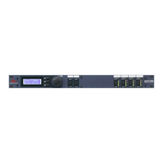
dbx ZonePRO Quick Start Manual
Browse online or download pdf Quick Start Manual for Computer Hardware dbx ZonePRO. dbx ZonePRO 2 pages. String calculator
Also for dbx ZonePRO: Quick Start Manual (6 pages)

801.566.8800
dbxpro.com
ZonePRO Quick Start Guide
PN: 5059564-A
© 2015 Harman. dbx Professional Products is a registered trademark of Harman. All rights reserved.
Quick Start Guide
WHAT'S IN THE BOX
• ZonePRO Processor
• Power Cable
• RS-232 Null Modem Cable
• Rack Mount Screw Kit
PRODUCT REGISTRATION
Register your product at http://dbxpro.com/en-US/
support/warranty_registration or scan the code to the
right with a QR scanner app on your mobile device.
DOWNLOAD THE INSTALL GUIDE
Get the install guide at http://dbxpro.com/en-US/
products/1260#documentation or scan the code to the
right with a QR scanner app on your mobile device.
WATCH THE TRAINING VIDEOS
Watch the ZonePRO training videos at http://dbxpro.
com/en-US/training or scan the code to the right with a
QR scanner app on your mobile device.
SELECT
SELECT
SELECT
SELECT
SELECT
SELECT
1
Download & Install ZonePRO Designer
Download and install the latest version of the ZonePRO Designer software application
from http://dbxpro.com/en-US/software.
NOTE: It is recommended that virus protection/malware software be disabled during
ZonePRO Designer installation.
2
Connecting Zone Controllers
Zone Controllers (ZCs) must be connected in a daisy-chain fashion using straight-through
CAT5 cables. The below diagram shows the maximum number of 12 ZCs connected to
a ZonePRO device, how each ZC's DIP switches would be assigned, and how the ZC ID
assignments match up with the ZonePRO Designer programming.
ID #s 1-6
(Top ZC Input Port)
ZonePRO Designer
DIP
Software Programming
Switches ZCs
ZC INPUT
ID#1
ZC-1
VOLUME
3
4
6
7
5
2
1
9
8
0
10
ID#2
ZC-3
SELECT
B
A
D
C
B
A
D
C
ID#3
ZC-1
ZC INPUT
VOLUME
4
3
6
5
7
1
2
8
9
0
10
ID#4
ZC-3
SELECT
B
A
D
C
A
B
C
D
ID#5
ZC-1
VOLUME
3
4
6
5
7
2
1
8
9
0
10
ID#6
ZC-3
SELECT
A
B
D
C
A
C
B
D
NOTE: If using a ZC-BOB, all CAT5 cables must be home run from each ZC to the ZC-
BOB. Daisy chaining ZCs off the ZC-BOB is not supported. A ZC must be configured as
ID #1 to be used for scene control and a ZC-FIRE must be configured as ID #2.
one
Z
PRO
1260
Digital Zone Processor
Digital Zone Processor
SELECT
SELECT
ID #s 7-12
(Bottom ZC Input Port)
ZonePRO Designer
DIP
Software Programming
ZCs
Switches
ZC-1
ID #7
VOLUME
4
3
5
6
7
2
1
8
9
0
10
ZC-3
ID#8
SELECT
B
A
D
C
B
A
D
C
ZC-1
ID#9
VOLUME
3
4
5
6
7
1
2
9
8
0
10
ZC-3
ID#10
SELECT
A
B
D
C
A
B
C
D
ZC-1
ID#11
VOLUME
3
4
5
6
7
2
1
8
9
0
10
ID#12
ZC-3
SELECT
A
B
D
C
A
B
C
D
