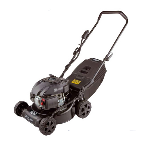
909 ES99 Instruction Manual - Page 11
Browse online or download pdf Instruction Manual for Lawn Mower 909 ES99. 909 ES99 20 pages. 99cc 400mm (16") electric start 4 stroke petrol lawn mower

Assembly
WARNING:
Stop the engine and unplug the spark plug
before any repairs or maintenance operations.
WARNING:
DO NOT attempt to start this mower without
first adding 0.4L of SAE 10W/30 engine oil to the
Engine. Refer Page 10.
WARNING:
Do Not attempt to start this mower without
the mower first being FULLY assembled.
It is necessary to fit the lower handle (2), handle bar (1),
and catcher (7) to the mower.
Attaching the handles
It is necessary to attach both the
lower handles and handle bars.
1. To attach the lower handles
(2), firstly unfold the handles
from the mower after removing
from the packaging, and raise
the cutting height adjustment
to the maximum height using
the height adjustment lever
(8). Locate the left hand lower
handle onto the outside of the
left hand mower handle mount
plate.
2. Align the holes of the handle
with the holes in the mount
plate.
3. Fit the small handle retaining bolts through the two mount
holes from within to without.
Retain the bolts with two locking knobs on the outside of
the handle tube.
4. Repeat the steps 1, 2, and 3 for the right hand Side.
Recheck all 4 handle mount bolts and knobs. Ensure the
knobs are firm and secure.
5. Unfold the top handle bars and when aligned with the
lower handles, lock the two handles together by pushing
the handle locking levers backwards. To release the
handles to pivot at any stage, pull the locking levers
forwards towards the top of the handle bars.
6. Once the handles are secured
the recoil start cord can be
positioned into the recoil starter
eyelet (22) for easier pull
starting. Pass the cord through
the overlap gap in the eyelet,
ensuring the cord passes
through with no restriction of
the centre hole of the eyelet.
Assembling the catcher
1. The grass catcher (5) is
supplied in two sections.
Locate the top half on top of
the bottom half and interlock
them together by aligning the
lugs and slots and pushing the
halves together until they click
into place.
Attaching the catcher
1. Lift the discharge guard (15) in
order to position the catcher.
2. While lifting the discharge
guard, align the holes in the
lower half of the catcher with
the hooks on the mower deck
(located under the discharge
chute). Push the catcher onto
the hooks in a downwards
direction.
11
