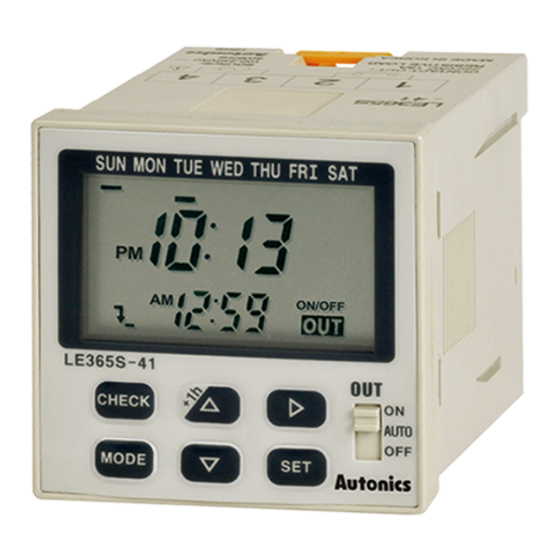
Autonics LE365S-41 Manual
Browse online or download pdf Manual for Timer Autonics LE365S-41. Autonics LE365S-41 12 pages. W48×h48mm, weekly/yearly timer
Also for Autonics LE365S-41: Mounting (11 pages)

LE365S-41
W48×H48mm, Weekly/Yearly Timer
Features
● Easy to check and change the program setting
● Customizable weekly or yearly unit time setting and
control by user
● Includes daylight saving time function
● 1 independent control output. (relay)
● Flush and surface, DIN rail mounting are in one unit.
Please read "Caution for your safety" in operation
manual before using.
Ordering Information
LE365
S
4
Size
Item
Specifications
Model
Power supply
Allowable voltage range
Power consumption
Timing program
Operation mode
Mounting
Time deviation
Temperature error
Memory protection
Contact type
Control
Contact capacity
Output
Output number
Mechanical
Relay
life cycle
Electrical
Insulation resistance
Dielectric strength
Noise immunity
Ambient temperature -10 to 55℃, storage: -25 to 65℃
Environment
Ambient humidity
Unit weight
※ Environment resistance is rated at no freezing or condensation.
Connections
1
CONTACT OUT:
250VAC 15A,
30VDC 5A
RESISTIVE LOAD
1
Output
1
Power supply
4
S
LE365
LE365S-41
100-240VACᜠ 50/60Hz
90 to 110% of rated voltage
Max. 2.4VA (100-240VACᜠ)
48 steps for weekly, 24 steps for yearly
ON/OFF mode, cycle mode, pulse mode
Panel flush, surface, DIN rail
±15sec/month (ambient temperature: 25℃) (±4sec/week)
±0.01% ±0.05sec
Over 5 years (at 25℃)
SPST (Single Pole Single Throw)
250VACᜠ 15A, 30VDCᜡ 5A resistive load
Independent 1 output (1a)
Min. 5,000,000 operations (switching capacity 30 times/min)
50,000 operations<switching capacity 20 times/min, 250VAC 15A (resistive load)>
Over 100MΩ (at 500VDC megger)
2,000VAC 50/60Hz for 1minute
±2kV the square wave noise (pulse width: 1μs) by the noise simulator
35 to 85%RH
Approx. 110g
2
3
4
SOURCE:
100-240VAC
50/60Hz
Weekly/Yearly Timer
1 Relay output
100-240VAC 50/60Hz
DIN W48×H48mm
Weekly/Yearly timer
(A)
Photoelectric
Sensors
(B)
Fiber
Optic
Sensors
(C)
Door/Area
Sensors
(D)
Proximity
Sensors
(E)
Pressure
Sensors
(F)
Rotary
Encoders
(G)
Connectors/
Connector Cables/
Sensor Distribution
Boxes/Sockets
(H)
Temperature
Controllers
(I)
SSRs / Power
Controllers
(J)
Counters
(K)
Timers
(L)
Panel
Meters
(M)
Tacho /
Speed / Pulse
Meters
(N)
Display
Units
(O)
Sensor
Controllers
(P)
Switching
Mode Power
Supplies
(Q)
Stepper Motors
& Drivers
& Controllers
(R)
Graphic/
Logic
Panels
(S)
Field
Network
Devices
(T)
Software
K-89
