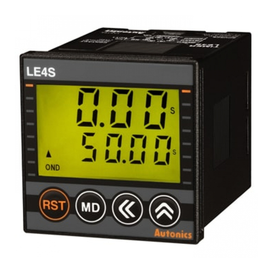
Autonics LE4SA Instruction - Page 4
Browse online or download pdf Instruction for Timer Autonics LE4SA. Autonics LE4SA 18 pages. Din w48xh48mm digital backlight lcd timer
Also for Autonics LE4SA: Manual (17 pages)

Input connections
LE4S is No-voltage input(Short-circuit and open) type.
Solid-state input
Sensor
12-24VDC
+
-
Q1
● Q1 is ON : Operating
● Sensor : NPN open collector output
※ Be sure that it is not insulated between power and input terminal block.
Parts description
● Output display
It displays the status
of output contact.
● UP/DOWN
It displays time progressing
UP(▲), DOWN(▼).
● Key lock display
It displays the status
of key lock.
● RESET key
Used for initializing time progressing
and output return.
Sensor
LE4S
START
RL
RESET
INHIBIT
Q2
Input 0V
● Q2 is ON : Operating
● Sensor : NPN universal output
LCD Timer(Touch Type)
Contact input
LE4S
12-24VDC
+
START
-
RESET
INHIBIT
Input 0V
● Time progressing display
It displays the current time.
● Time unit
It displays the time unit.
(h:hour)(m:min.)(s:sec.)
※ When the time is progressing, it
is flashing at a rate of (0.5sec.)
● Time setting display
It displays the setting time.
● Operation mode
It displays the current operation mode.
(ex: OND=ON Delay)
● SHIFT key
Used for advancing to setting time change
mode and moving to each digit.
● UP key
Used for advancing to function setting
mode, setting time change checking.
● MODE key
Used for changing the set value.
LE4S
START
RESET
S1
INHIBIT
S2
S3
Input 0V
● S1, S2, S3 are ON : Operating
● Please use reliable contact
enough to flow 5VDC 1mA.
(A)
Photo
electric
sensor
(B)
Fiber
optic
sensor
(C)
Door/Area
sensor
(D)
Proximity
sensor
(E)
Pressure
sensor
(F)
Rotary
encoder
(G)
Connector/
Socket
(H)
Temp.
controller
(I)
SSR/
Power
controller
(J)
Counter
(K)
Timer
(L)
Panel
meter
(M)
Tacho/
Speed/ Pulse
meter
(N)
Display
unit
(O)
Sensor
controller
(P)
Switching
mode power
supply
(Q)
Stepper
motor&
Driver&Controller
(R)
Graphic/
Logic
panel
(S)
Field
network
device
(T)
Software
(U)
Other
K-23
