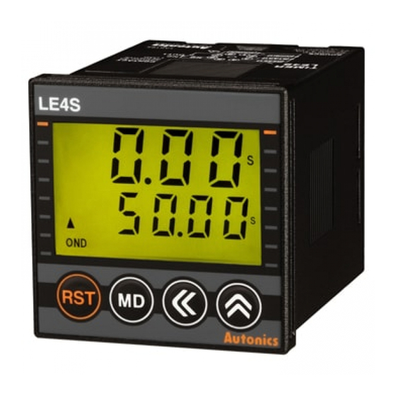
Autonics LE4SA Manual - Page 15
Browse online or download pdf Manual for Timer Autonics LE4SA. Autonics LE4SA 17 pages. Din w48xh48mm digital backlight lcd timer
Also for Autonics LE4SA: Instruction (18 pages)

LE4SA Output Operation Mode
Mode
Time chart
[
]
INT
Time limit contact
Instantaneous contact
Setting time
UP
Setting time
Interval
DOWN
1. Time limit output will be ON when power is ON and Timing operation starts.
2. Time limit output will be OFF when timing operation is progressed up to the setting time. Display value will be
HOLD.
3. If selecting time limit 1c + instantaneous 1c mode, instantaneous output will be ON when power is ON and
goes OFF when power is OFF.
4. If pressing RESET key, display value and time limit output will be reset.
[
]
-
※ RESET
contact (⑧-⑥)
contact (①-③)
Setting time
Star-Delta
UP
Setting time
(output will be set
DOWN
automatically
1.
contact will be ON when power is ON and Timing operation starts.
as Time limit 2c)
2.
contact will be OFF when timing operation is progressed up to the T1 setting time.
Timing operation will be reset and started again.
3.
contact will be ON when timing operation is progressed up to the T2 switching time.
Display value will be HOLD.
4. If pressing RESET key, display value and
5. It is able to set each T1 and T2 time separately.
[
]
T
※ RESET
T1 contact (⑧-⑥)
T2 contact (①-③)
Setting time
Twin
UP
Setting time T1
(output will be set
automatically
DOWN
as Time limit 2c)
1. T1 contact will be ON when power is ON and Timing operation starts.
2. T1 contact will be OFF and T2 contact will be ON when timing operation is progressed up to the T1 setting
time. Timing operation will be reset and started again. T2 contact will be OFF when timing operation is
progressed up to the T2 setting time. Display value will be HOLD.
3. If pressing RESET key, display value and T1, T2 contacts will be reset.
4. It is able to set each T1 and T2 time separately.
[
]
TⅠ
T1 contact (⑧-⑥)
T2 contact (①-③)
Setting time
Twin 1
UP
Setting time T1
(output will be set
DOWN
automatically
as Time limit 2c)
1. Timing operation starts when power is ON.
2. T1 contact will be ON when timing operation is progressed up to the T1 setting time. Timing operation will be
reset and started again.
3. T2 contact will be ON when timing operation is progressed up to the T2 setting time. Display value will be
HOLD.
4. If pressing RESET key, display value and T1 and T2 contacts will be reset.
5. It is able to set each T1 and T2 time separately.
※ Initial status: UP mode-display value is "0", output is "OFF". DOWN mode-display value is "setting time", output is "OFF".
※ Instantaneous contact (OUT2) will be returned when power is off.
※ RESET key is locked for default set and release the lock to use.
T
Rt
POWER
※ RESET
(⑧-⑥)
(①-③)
0
0
T1
T2
POWER
T1
T2
0
T1
T2
0
-
contacts will be reset.
T1
T2
POWER
T1
T2
0
T2
0
T1
T2
POWER
※ RESET
T1
T2
0
T2
0
LCD Display Timer
T
T
Rt
T1
T2
Rt
T1
T2
T1
Ta
Rt
T1
T2
Rt: Reset time (min. 500ms)
Operation
SENSORS
CONTROLLERS
POWER
MOTION DEVICES
T
Time limit
contact
SOFTWARE
output
T = set time
(J)
Temperature
Controllers
POWER
(K)
T1
SSRs
contact
T2
(L)
Power
contact
Controllers
※ T1: set time
(M)
Counters
T2: switching time
( - switching time)
(N)
Timers
(O)
Digital
Panel Meters
POWER
(P)
T1
Indicators
T1 contact
T2
(Q)
Converters
T2 contact
T1, T2 = set time
(R)
Digital
Display Units
Enables to set T1 and T2
time same or differently
(S)
Sensor
Controllers
(T)
Switching
Mode Power
Supplies
(U)
POWER
Recorders
T1
T1 contact
(V)
T2
HMIs
T2 contact
(W)
T1, T2 = set time
Panel PC
Enables to set T1 and T2
(X)
time same or differently
Field Network
Devices
N-37
