Autonics EP50S8 N Series Product Manual - Page 2
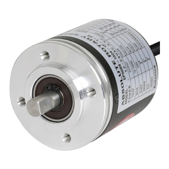
Browse online or download pdf Product Manual for Media Converter Autonics EP50S8 N Series. Autonics EP50S8 N Series 3 pages. 50 mm diameter absolute single-turn rotary encoders
Cautions during Installation
• Install the unit correctly with the usage environment, location, and the designated
specifications.
• Do not load overweight on the shaft.
• Do not put strong impact when insert a coupling into shaft.
Failure to follow this instruction may result in product damage.
• When fixing the product or coupling with a wrench, tighten under 0.15 N m.
• If the coupling error (parallel misalignment, angular misalignment) between the shaft
increases while installation, the life cycle of the coupling and the encoder can be
shorten.
• Do not apply tensile strength over 30 N to the cable.
Ordering Information
This is only for reference, the actual prodcut does not support all combinations.
For selecting the specified model, follow the Autonics website.
EP50
S
8
-
❶
❶ Resolution
Number: Refer to resolution in 'Output
Phase / Output Angle'
❷ Output code
1: BCD code
2: Binary code
3: Gray code
❸ Rotating direction
F: Increase output when the rotating
direction is clockwise base on facing
the shaft
R: Increase output when the rotating
direction is counter-clockwise base on
facing the shaft
Product Components
• Product
• Instruction manual
Connections
• Unused wires must be insulated.
• The metal case and shield cable of encoders must be grounded (F.G.).
• F.G. (Frame Ground) must be grounded separately.
• Since exclusive driver IC is used for output circuit, be aware of short circuits when
wiring each output wires.
• N·C: not connected
■ BCD code
Color
Function Refer
White
+V
Power
Black
GND
Brown
2
0
Red
2
1
Orange
2
2
Yellow
2
3
Blue
2
× 10
0
Purple
2
× 10
1
Gray
2
× 10
2
TP1
White / Brown 2
× 10
3
(≤ 40 division)
TP2
White / Red
2
× 10
0
2
(≤ 40 division)
EP
White / Orange 2
× 10
1
2
(≤ 40 division)
White / Yellow
2
× 10
2
2
White / Blue
2
× 10
3
2
White / Purple 2
× 10
0
3
Shield
F.G.
Signal shield
-
❷
❸
-
❹
-
❹ Control output
N: NPN open collector output
P: PNP open collector output
❺ Power supply
5: 5 VDCᜡ ±5%
24: 12 - 24 VDCᜡ ±5%
• Bolt × 8
• Coupling × 1
• Bracket × 2
■ Binary / Gray code
Color
Function Refer
White
+V
Power
Black
GND
Brown
2
0
Red
2
1
Orange
2
2
Yellow
2
3
Blue
2
4
Purple
2
5
Gray
2
6
TP1
White / Brown 2
7
(≤ 40 division)
TP2
White / Red
2
8
(≤ 40 division)
EP
White / Orange 2
9
(≤ 40 division)
White / Yellow
N·C
White / Blue
N·C
White / Purple N·C
Shield
F.G.
Signal shield
Inner Circuit
• The output circuit is identical for each output bit.
• Be aware of circuit break in case of overload or short beyond the specifications.
■ PNP open collector output
Output Waveform
• Following waveform is based on the positive logic.
(In case of negative logic, the waveform is opposite to corresponding waveform.)
■ BCD code output
❺
0
1
2
3
4
5
6
2
0
TS
2
1
2
2
2
3
.
.
.
2
× 10
3
2
2
× 10
0
3
■ Binary code output
0
1
2
3
4
5
6
7
8
2
0
TS
2
1
2
2
2
3
.
.
.
2
8
2
9
Specifications
Model
EP50S8-▭-□□-N-□
Resolution
≤ 1024 division
01)
Output code
BCD / Binary / Gray code model
Control output
NPN open collector output
Inflow current
≤ 32 mA
Residual voltage
≤ 1 VDCᜡ
Outflow current
-
Output voltage
-
Response speed
T
02)
on
Max. response freq.
35 kHz
Max. allowable
3,000 rpm
revolution
03)
Starting torque
≤ 0.0069 N m
Inertia moment
≤ 40 g·cm
Allowable shaft load Radial: 10 kgf, Thrust: 2.5 kgf
Unit weight
≈ 398 g (≈ 482 g)
(packaged)
Approval
ᜢ ᜫ
01) Refer to resolution in 'Output Phase / Output Angle'.
02) Based on cable length: 2 m, I sink = 32 mA
03) Select resolution to satisfy Max. allowable revolution ≥ Max. response revolution
[max. response revolution (rpm) =
5 VDCᜡ ± 5% (ripple P-P: ≤ 5%) /
Power supply
12 - 24 VDCᜡ ± 5% (ripple P-P: ≤ 5%) model
Current consumption ≤ 100 mA (no load)
Insulation resistance Between all terminals and case: ≥ 100 MΩ (500 VDCᜡ megger)
Dielectric strength
Between all terminals and case: 750 VACᜠ 50 / 60 Hz for 1 minute
1 mm double amplitude at frequency 10 to 55 Hz (for 1 minute) in each
Vibration
X, Y, Z direction for 2 hours
Shock
≲ 50 G
Ambient temp.
-10 to 70 ℃, storage: -25 to 85 ℃ (no freezing or condensation)
Ambient humi.
35 to 85%RH, storage: 35 to 90%RH (no freezing or condensation)
Protection rating
IP65 (IEC standard)
Connection
Axial cable type (cable gland)
Cable spec.
Ø 7 mm, 15-wire, 2m, shield cable
01)
Wire spec.
AWG28 (0.08 mm, 40-core), insulator diameter: Ø 0.8 mm
01) Oil-resistant PVC shield cable option is also available to order.
■ NPN open collector output
Max. 32 mA
LOAD
7
8
9
1020
1021
1022
1023
0'
■ Gray code output
9
1020
1021
1022
1023
0'
0
1
2
3
4
5
2
0
TS
2
1
2
2
2
3
.
.
.
2
8
2
9
EP50S8-▭-□□-P-□
PNP open collector output
-
-
≤ 32 mA
≥ (power supply -1.5) VDCᜡ
≤ 800 nsec, T
≤ 800 nsec
off
(4 × 10
kg·m
)
2
-6
2
max. response frequency
× 60 sec
]
resolution
LOAD
Max. 32 mA
6
7
8
9
1020
1021
1022
1023
0'