Autonics EPM50 Series Product Manual - Page 2
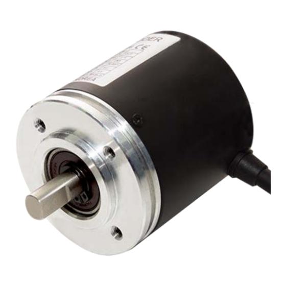
Browse online or download pdf Product Manual for Media Converter Autonics EPM50 Series. Autonics EPM50 Series 4 pages. 50 mm diameter absolute multi-turn rotary encoders
Cautions during Installation
• Install the unit correctly with the usage environment, location, and the designated
specifications.
• Do not load overweight on the shaft.
• Do not put strong impact when insert a coupling into shaft.
Failure to follow this instruction may result in product damage.
• When fixing the product or coupling with a wrench, tighten under 0.15 N m.
• If the coupling error (parallel misalignment, angular misalignment) between the shaft
increases while installation, the life cycle of the coupling and the encoder can be
shorten.
• Do not apply tensile strength over 30 N to the cable.
Ordering Information
This is only for reference, the actual prodcut does not support all combinations.
For selecting the specified model, follow the Autonics website.
EPM50
S
8
- 10 13 -
❶ Control output
PN: Parallel NPN open collector output
S: SSI Line driver output
Product Components
• Product
• Instruction manual
Connections
• Unused wires must be insulated.
• The metal case and shield cable of encoders must be grounded (F.G.).
• F.G. (Frame Ground) must be grounded separately.
• For Parallel NPN open collector output, it is recommended to connect +V and GND of
both multi-turn count cable and single-turn data cable.
• Since exclusive driver IC is used for output circuit, be aware of short circuits when
wiring each output wires.
• N·C: not connected
■ Parallel NPN open collector output
• Multi-turn count (sheath: black)
Color
Function
Refer
White
+V
Power
Black
GND
Brown
2
0
Red
2
1
Orange
2
2
Yellow
2
3
Green
2
4
Blue
2
5
Multi-turn
Purple
2
6
count
Gray
2
7
Pink
2
8
Clear
2
9
Light brown 2
10
Light yellow 2
11
2
Light green
12
Light blue
Overflow alarm (OVF)
Light purple Multi-turn count reset
Shield
F.G.
Signal shield
■ SSI Line driver output
Color
Function
Refer
+V
White
Power
Black
GND
Brown
CLOCK+
Red
CLOCK-
SSI
Orange
DATA+
Yellow
DATA-
Single-turn
Gray
data reset
Multi-turn
Blue
COMMAND
count reset
Purple
Clear
Green
Direction
Shield
F.G.
Signal shield
B
-
❶
- 24 -
❷ Connection
No mark: Axial cable type
S: Radial cable type
• Bolt × 8
• Coupling × 1
• Bracket × 2
• Single-turn data (sheath: gray)
Color
Function
Refer
White
+V
Power
Black
GND
Brown
2
0
Red
2
1
Orange
2
2
Yellow
2
3
Green
2
4
Single-turn
data
Blue
2
5
Purple
2
6
Gray
2
7
Pink
2
8
Clear
2
9
Light brown N·C
Light yellow Direction
Latch
Light green
Light blue
Clear
Light purple Single-turn data reset
F.G.
Signal shield
Shield
Inner Circuit
• The output circuit is identical for each output bit.
• Be aware of circuit break in case of overload or short beyond the specifications.
■ Parallel NPN open collector output
• COMMAND input
Single-turn data reset
Multi-turn count reset
Direction
Clear
Latch
■ SSI Line driver output
• CLOCK input
❷
• Output
Data+
Data-
Dimensions
• Unit: mm, For the detailed drawings, follow the Autonics website.
■ Parallele NPN open collector output
Ø 38
4-M4 DP 10
■ SSI Line driver output
Ø 38
4-M4 DP 10
■ Bracket
4.5
2.5
R2.2
14.5
• Output
• COMMAND input
Clock+
Clock-
15
56
3
3.5
7
0
-0.1
10
15
56
3
3.5
7
0
-0.1
10
■ Coupling
Ø 19
Ø 8
+0.1
0
• Parallel misalignment: ≤ 0.25 mm
• Angular misalignment: ≤ 5°
• End-play: ≤ 0.5 mm
Single-turn data
Multi-turn count
OVF
Single-turn data reset
Multi-turn count reset
Direction
Clear
20
8
Ø 6, 2 m
Ø 6, 2 m
20
8
Ø 6, 2 m
25
3.4
3.4
4-M4