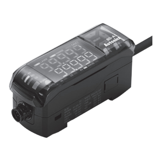
Autonics BD-A1 Product Manual - Page 2
Browse online or download pdf Product Manual for Security Sensors Autonics BD-A1. Autonics BD-A1 3 pages. Laser displacement sensors amplifier unit
Also for Autonics BD-A1: Manual (14 pages)

Product Components
• Amplifier unit
• Instruction manual
Sold Separately
• Laser displacement sensor communication converter: BD-C Series
• Fixing bracket (BK-BD-C)
Manual
For proper use of the product, refer to the manuals and be sure to follow the safety
considerations in the manuals.
Download the manuals from the Autonics website.
Specifications
Model
BD-A1
10 - 30 VDCᜡ ±10% (when connecting BD-C, communication
Power supply
converter, 12-30 VDCᜡ)
Power consumption
≤ 2,800 mW (30 VDCᜡ)
01)
Hold trigger, Output reset, Laser OFF, Zero-point adjustment,
Control Input
BANK-A/B combinations : No-voltage input
Judgment output
NPN or PNP open collector (load current: ≤ 100 mA)
(HIGH/GO/LOW)
Alarm output
NPN or PNP open collector (load current: ≤ 100 mA)
Voltage: -5 - 5 V, 0 - 5 V, 1 - 5 V
(resistance: 100 Ω, ± 0.05% F.S., at 10 V)
Analog output
Current: 4 - 20 mA 4 - 20 mA
(load resistance: ≤ 350 Ω, ± 0.2% F.S., at 16 mA)
Residual voltage
NPN: ≤ 1.5 V, PNP: ≤ 2.5 V
Reverse polarity protection circuit, output over current (short-
Protection circuit
circuit) protection circuit
Response Time
0.33 / 0.5 / 1 / 2 / 5 ms
[BD-030 / 065 / 100] 1 ㎛
Min. display unit
[BD-300 / 600] 10 ㎛
Display type
11 segment (red, green), 6-digit, LED
[BD-030 / 065 / 100] ± 99.999 to ± 99 mm (4-step paramete set)
Display range
03)
[BD-300 / 600] ± 999.99 to ± 999 mm (3-step parameter set)
Display period
≈ 100 ms
Insulation resistance
≥ 20 MΩ (500 VDCᜡ megger)
Square shaped noise by noise simulator (pulse width: 1 ㎲) ±
Noise immunity
500 V
Between the charging part and the case: 1,000 VACᜠ 50/60 Hz for
Dielectric strength
1 minute
1.5 mm amplitude at frequency of 10 to 55 Hz in each X, Y, Z
Vibration
direction for 2 hours
Shock
300 m/s
(approx. 30 G) in each X, Y, Z direction for 3 times
2
Ambient temperature
-10 to 50 ℃, Storage: -15 to 60 ℃ (no freezing or condensation)
Ambient humidity
≤ 85%RH, Storage: ≤ 85%RH (no freezing or condensation)
Material
Case: PC, Cover: PC, cable: PVC
Supported sensor head
Sensor head (BD-□)
Supported
Communication converter (BD-C)
comunication converter
Protection structure
IP40 (IEC standard)
Approval
ᜢ ᜧ ᜫ
Unit weight (packaged)
≈ 126 g (≈ 228 g)
01) Power to the load is not included.
02) Sensor head model BD-600 displays values per min. display unit (10 ㎛) but actual value is increased/
decreased per 20 ㎛.
03) Setting range is assigned automatically when connecting sensor head.
04) Sensor head model BD-300/600 supports only over 5.0 firmware version of the amplifier unit (BD-A1).
05) The communication converter (BD-C) over 5.0 firmware version of supports only over 5.0 firmware version of
the amplifier unit (BD-A1).
Dimensions
• Unit: mm, For the detailed drawings, follow the Autonics website.
30
87.35
35 mm
DIN rail
• Fixing bracket (BK-BD-C)
• Side connector
02)
04)
05)
Fixing Bracket (BK-BD-C)
35
21
2-Ø1.9
7
6-R1.6
14
31.2
2
Ø4.8, 2 m
2-Ø3.2
27
Unit Descriptions
10
4
1
5
2
3
6
3. SV display recognition indicator (green)
HI: HIGH judgment value
LO: LOW judgment value
RV: Real distance value
ANALOG: Analog output
4. Judgment indicator
HI (red) / GO (green) / LO (red)
5. Alarm indicator (red)
6. Emission optimization setting key
[AUTO]
Control Output Diagram
■ Judgment (HIGH, GO, LOW) and alarm output
• NPN open collector output
LOAD
≤ 100 mA
OCP
30 VDCᜡ
SCP
LOAD
■ Analog output
+
+
• OCP (Over Current Protection), SCP (Short Circuit
mA
Protection)
-
-
• The control output is abnormal when the control output
circuit is shorted or over current is supplied.
Installation Step 1. Installation Precautions
• Do not supply the power when adding amplifier unit.
• Supply power to each connected amplifier unit at the same time.
• Up to 8 amplifier units can be connected
• The function can be set using the master amplifier unit, and measurements are
made according to the corresponding setting value.
• Only 1 calculation function can be performed per 1 group of mutually connected
amplifiers.
When the calculation function is activated, the SV of the slave units are disable and the
mutual interference prevention function for sensor heads is executed automatically.
• Check the compatible firmware version when connecting the sensor head or
communication converter to the amplifier unit.
Installation Step 2. Connect amplifier unit
■ Connecting amplifier units mutually
②
①
③
■ Distinguishing master/slave amplifier units
When the power cable direction is down, the amplifier at the left end is the master unit,
and the channel number of slaves increases sequentially to the right.
Master
1. PV display (red)
Displays PV (present value),
▲
calculating result (when using
9
calculation), parameter name
◀
▶
(when setting parameter).
▼
2. SV display (green)
Displays SV (setting value),
parameter setting value (when
setting parameter).
7
8
7. Zero-point adjustment setting key
[ZERO]
8. Mode setting key [MODE]
9. Direction key [◀], [▶], [▲], [▼]
10. Status indicator (green)
CALC: Calculation indicator
RANGE: Turns on within measurement range,
Turns off when out of range or laser emission
stops
LASER: Laser emission indicator
• PNP open collector output
LOAD
30 VDCᜡ
OCP
SCP
≤ 100 mA
LOAD
1. Remove the side cover at the connecting
side.
2. Connect the side connector to the units.
3. After mounting amplifier unit on DIN
rail, push it to arrow direction tightly.
• In case of disconnecting, follow the
upper sequence reversely.
• Max. 8 units
Slave
