Autonics ARD-DX16N Manual - Page 8
Browse online or download pdf Manual for I/O Systems Autonics ARD-DX16N. Autonics ARD-DX16N 8 pages. Devicenet digital remote i/o
Also for Autonics ARD-DX16N: Manual (8 pages)

ARD-D Series
Setup and Installation
Mounting on DIN rail
① Pull Rail Locks (standard terminal block type: 3EA, sensor connector type: 2EA)
on the rear part of unit.
② Place the unit on DIN rail to be mounted.
③ Press Rail Locks to fix the unit tightly.
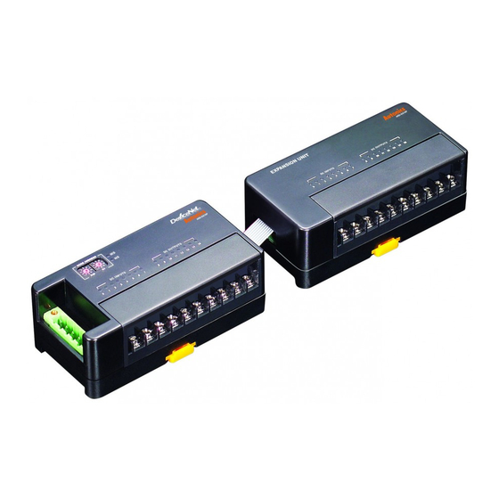
Connection of basic unit and expansion units
(standard terminal block type)
① Turn OFF the power of a Basic unit.
② Place an expansion unit to be installed next to the basic unit.
③ Connect the cable of expansion unit to the connector of a basic unit.
④ Install a connected expansion units as the right figures.
⑤ Supply the power to a Basic unit.
(Re-supply the power of a basic unit and it recognizes expansion units.)
Connection of basic unit and expansion units
(sensor connector type)
① Turn OFF the power of the basic unit.
② Remove a cover of connector for extension with nippers, etc.
③ Connect connector input part of an expansion unit and connector output
part of a basic unit with a connector which is enclosed with an expansion unit box.
④ Install a connected expansion units as the right figure.
⑤ Supply the power to the Basic unit.
(Re-supply the power of a basic unit and it recognizes expansion units.)
Communication Distance
Baud Rate
Max. network length
125kbps
500m
250kbps
250m
500kbps
100m
Terminating Resistance
● 120Ω ● 1% of metallic film
※ Do not install terminating resistance on the unit, or it may cause network terminating problem (Impedance can be too high
or low) and trouble.
※ Connect terminating resistance on the both ends of the trunk line.
Caution During Use
Turn OFF the power before connecting or disconnecting expansion units.
Node addresses of connected units on network should not be duplicated. If you change a node address during
operation,unit status (MS) red LED fl ashes and it communicates with a previous node address.
Re-supply power and the changed node address is applied.
Communication speed which is set on master is set automatically. If you change the communication speed during
operation, network status (NS) red LED turns ON and it does not communicate.
Re-supply power and it operates normally.
Make sure to use DeviceNet standards communication cables, and taps.
It may cause communication error if non-standards products are used.
Make sure to examine disconnection or short-circuit before connecting cables.
Avoid installing the units where severe dust exists or where corrosion may occur.
This unit may be used in the following environments.
• Indoor
• Altitude: Under 2,000m
• Pollution degree 2
• Installation category II
S-12
Max. branch line length
6m
6m
6m
● 1/4W
Max. extended branch line length
156m
78m
39m
