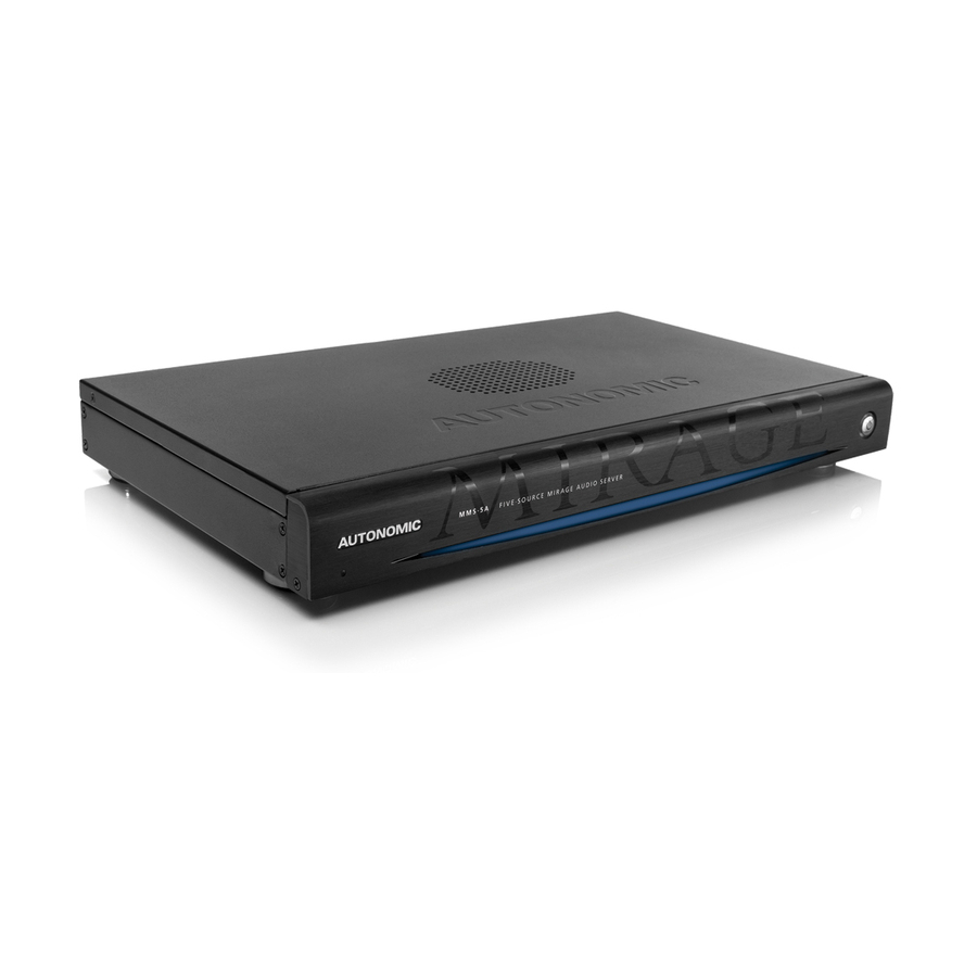
Autonomic MIRAGE Quick Start Manual - Page 2
Browse online or download pdf Quick Start Manual for Stereo System Autonomic MIRAGE. Autonomic MIRAGE 4 pages. Autonomic mirage audio system
Also for Autonomic MIRAGE: Quick Start Manual (3 pages)

1. HARDWARE PREPARATION
Connect to the Network
a.
Connect the server and amplifier to the network. If you have
multiple amplifiers, connect only the first amplifier to the network.
(See
Stacking
Amps, below.)
Expansion
ZONE 1
ZONE 2
ZONE 3
ZONE 4
ZONE 5
ZONE 6
ZONE 7
ZONE 8
IR OUTPUTS
Connect Digital Audio Cable
b.
Connect the coax digital output (labeled
Media Server) to the digital input
the M-800), leaving inputs with analog available to the analog
outputs of the Mirage Media Server.
Expansion
ZONE 1
ZONE 2
ZONE 3
ZONE 4
ZONE 5
ZONE 6
ZONE 7 ZONE 8
IR OUTPUTS
Connect Analog Audio Cables
c.
Connect the source inputs to the analog outputs in sequential order.
Expansion
ZONE 1
ZONE 2
ZONE 3
ZONE 4
ZONE 5
ZONE 6
ZONE 7 ZONE 8
IR OUTPUTS
Power On the Server
d.
Press the power button on the Mirage Media Server. The Mirage
Amplifier will power on when plugged in. It's recommended to
attach a display when first powering up the Mirage Media Server,
as the IP address will display on-screen.
e.
Wait 2–3 minutes for the server to run the initial boot-up.
f.
If your server is connected to a video display, wait until the Now
Playing screen shows.
Stacking Amps
If the system contains multiple Mirage
amplifiers, attach a standard, straight-
through cat 5 cable from the upper
Expansion Port on the first amplifier
to the lower Expansion Port on
subsequent amplifiers. Additionally, for
each source attach a coax RCA cable
from the source's digital output on the
first amplifier in the chain and so forth.
Repeat for each amplifier in the chain.
©2006–2016 Autonomic Controls, Inc. Autonomic and TuneBridge are registered trademarks of Autonomic Controls, Inc.
All other trademarks are property of their respective owners.
M-800
MIRAGE 8-ROOM
DIGITAL AMPLIFIER
Toslink
Main
on the Mirage
(S5
on the M-400), or
(S7
on
M-800
MIRAGE 8-ROOM
DIGITAL AMPLIFIER
Toslink
M-800
MIRAGE 8-ROOM
DIGITAL AMPLIFIER
Toslink
Subsequent M-800
or M-400 Amps
2nd Amp
Expansion
M-800
ZONE 1
ZONE 2
ZONE 3
MIRAGE 8-ROOM
DIGITAL AMPLIFIER
Toslink
ZONE 4
ZONE 5
ZONE 6
ZONE 7 ZONE 8
IR OUTPUTS
Expansion
1st Amp
ZONE 1
ZONE 2
ZONE 3
Expansion
M-800
MIRAGE 8-ROOM
ZONE 1
ZONE 2
ZONE 3
DIGITAL AMPLIFIER
ZONE 4
ZONE 5
ZONE 6
ZONE 7 ZONE 8
Toslink
ZONE 4
ZONE 5
ZONE 6
ZONE 7 ZONE 8
IR OUTPUTS
TYPICAL SYSTEM CONFIGURATION
Audio
LAN
Video
(Mac or PC)
Mirage Media Server
Video
Mirage Amplifier
ZONE 1
ZONE 2
ZONE 3
ZONE 4
ZONE 5
ZONE 6
Kitchen
Living Room
Main Room
Listening Room
A/V Receiver
2-Channel Amp
Identifying Multiple
Amps in a Stack
Use the amplifier's MAC address to identify
which amps connect to each zone.
M-800
MIRAGE 8-ROOM
DIGITAL AMPLIFIER
Toslink
Mac Address
IR OUTPUTS
KP-iOS
(MMS-5A Displayed in this diagram)
(M-800 Displayed in this diagram)
Expansion
M-800
MIRAGE 8-ROOM
DIGITAL AMPLIFIER
Toslink
ZONE 7
ZONE 8
IR OUTPUTS
Bedroom
Component Video
An HDMI-to-component
adapter is required to
connect component-based
video (not included)
On-Screen Navigation (OSN) with IR Remote
IR Remote included with MMS-5A only upon request
How to Find the Server's MAC Address
The MAC address of the server can be found on the
Server Settings
tab of the server's web configuration
listed next to
Wired
Ethernet.
KP-6
Patio
