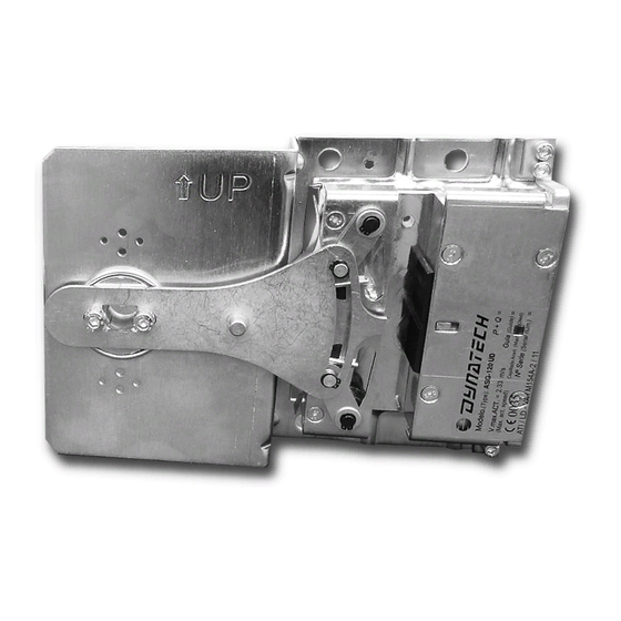
Dynatech PR-2500-UD Series Instructions For Use And Maintenance Manual - Page 14
Browse online or download pdf Instructions For Use And Maintenance Manual for Industrial Equipment Dynatech PR-2500-UD Series. Dynatech PR-2500-UD Series 19 pages. Progressive safety gear
Also for Dynatech PR-2500-UD Series: Instructions For Use Manual (11 pages)

INSTRUCTIONS : PR-2500-UD
Date: 15/04/2016
Revision: 08
Total clearance =
3.3 COUPLING THE DRIVING BAR
It is the responsibility of the person who installs the safety gear to properly position the driving bar in relation
to the safety gear, as well as to properly synchronise the safety gears controlled by that driving bar. The driving
bar is properly positioned when the trolley's pivot is in the protection plate's central position.
Once it has been fitted and the safety gear's roller's trolleys have been attached to the driving bar's tripping
bars, it should be checked that both trolleys operate simultaneously, controlled by the driving bar. This should
be checked in both directions, ascending and descending.
The overspeed governor should generate a minimum force that it should be twice the force to ensure the
synchronized performance of the safety gears.
⚠
The Standard demands that the installation incorporate an AC-15 or DC-13 safety contact as defined in
EN 60947-5-1.
USING DYNATECH'S T-2 DRIVING BAR
3.3.1
The PR-2500-UD.V35 safety gear may be synchronised by assembling Dynatech's T-2 driving bar. For more
information concerning T-2 driving bar assembly, please consult its manual: DYN06 – Instructions T-2.
⚠
T-2 driving bars cannot be used with PR-2500-UD.V50 safety gears
⚠
It is not recommended to exceed a maximum force of 1900 N is not recommended with the governor.
Cod : DYN 05.01.08
3.5 mm
Figure 8 Safety gear adjustment in relation to the guide rail
Figure 9: Safety gear synchronisation using the T-2 driving bar
Total clearance =
5 mm
7
