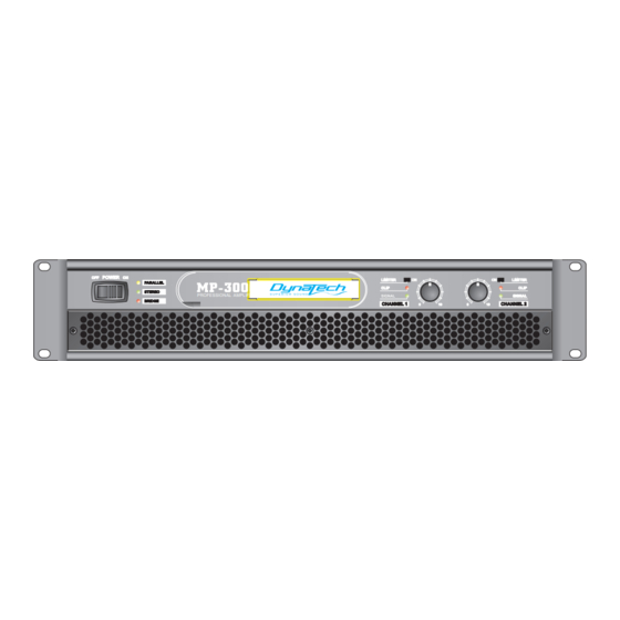
Dynatech MP-5000 Owner's Manual - Page 9
Browse online or download pdf Owner's Manual for Amplifier Dynatech MP-5000. Dynatech MP-5000 16 pages. Professional power amplifiers mp series

PROFESSIONAL POWER AMPLIFIERS
Connecting Power / Circuit Size Requirements.
MP Series amplifier power requirements are rated at:
a) "idle"
b) 1/8th power ("typical" music conditions)
c) 1/3rd power ("continuous" music conditions)
d.) maximum rated power ( under limited).
The maximum power current draw rating is limited only by the rear circuit breaker(3U MODEL) or the fuse
type (2U MODEL) . Consult the specifications section for figures on the current that each amplifier will
demand. Make sure the mains voltage is correct and is the same as that printed on the rear of the amplifier.
Damage caused by connecting the amplifier to improper AC voltage is not covered by any warranty.
Unless otherwise specified when ordered, DynaTech amplifiers shipped to customers are configured
as follows:
North America
Europe
Asia
Australasia
South America
Japan
NOTE: Always turn off and disconnect the amplifier from mains voltage before making audio connections.
Also, as an extra precaution, have the attenuators turned down during power-up.
Cooling System and Requirements.
MP Series amplifiers use a twin-tunnel forced-air cooling system to maintain a low, even operating tempera-
ture. Drawn out by dual 45 cubic feet-per-minute (CFM) fans on the rear panel, air flows from the front grill
and through the cooling fins of the channel heat sinks (dissipating power transistor heat), then exhausts thr-
ough the back panel ports. The "intelligent" variable-speed DC fans are controlled by heat sink temperature
sensing circuits. When the amplifier is turned on, the fans briefly "rev up," then slow to an idle; this indicates
that the temperature sensing circuits are operating normally. The fan speed increases only as required by
heat sink temperatures, keeping fan noise to a minimum. Under extreme thermal load, the fans will force a
very large volume of air through the heat sinks. If either heat sink surpasses the maximum allowed temper-
ature, the sensing circuit will shut down the output, no signal output to the load . If the power transformer
overheats, another sensing circuit shut down both channel output until the transformer cools to a safe temp-
erature.
IMPORTANT: To ensure optimum cooling, periodically clean the amplifier fan filters. Also make certain that
there is enough space around the back of the amplifier to allow the cooling air to escape. If the amplifier
s rack-mounted, do not use doors or covers on the front of the rack, the exhaust air must flow out without
resistance. If the amplifiers are to be housed in racks with closed backs, allow at least one (1) standard rack
space of opening in the front of the rack for every four amplifiers.
Connecting Inputs.
Use either the XLR or 1/4-inch input connectors on the rear to supply audio signals to your DynaTech MP
Series amplifier. Both connectors accept balanced and unbalanced audio connections. (The MP Series
amplifiers are configured standard with "Pin 2 hot" on XLR inputs. Please note that some other Audio
amplifiers are configured with "Pin 3 hot"). The unused connector can be used to jumper the audio input
to another amplifier input.
Connecting Outputs.
Speakers are connected using Output Binding Posts or Speakon connectors, For more information, see the
Mode Selection sections.
Page 8
MP SERIES
MP-3000 (2U MODEL)
MP-4000 MP-5000 MP-7000 ( 3U MODEL)
Operation
120VAC / 60Hz
230VAC / 50Hz
220VAC / 50Hz
240VAC / 50Hz
120VAC / 60Hz or 220VAC / 50Hz
100VAC / 50Hz
Connecting amplifier outputs to oscilloscopes or other test equipment while the
amplifier is in bridged mode may damage both the amplifier and test equipment!
Operation
