Dynatech V PLUS Series User Instruction - Page 5
Browse online or download pdf User Instruction for Amplifier Dynatech V PLUS Series. Dynatech V PLUS Series 14 pages.

P R O F E S S I O N A L
P O W E R
A M P L I F I E R
Front Views & Rear Views | Introduction |
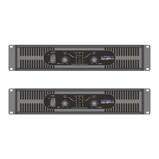
V-3000 PLUS / V-4000 PLUS Front Panel
1
1. Rack Mounting Ears - Two front panel mounting holes are provided on each mounting ear.
2. AC Power Switch - V PLUS Series amplifiers have a front-panel mains AC power switch.
3. Mode Indicated LED - Green LED indicates "parallel" Mode, Blue LED indicates "stereo" Mode, Green
indicates "bridge" Mode.
4. DynaTech Logo and Model No - V PLUS Series have 2 types of 2U models V-3000 Plus and V-4000 Plus.
5. Fan Inlet Grills and Filter -V PLUS Series amplifiers are cooled by two rear-mounted fans. Cool air from front
grills are filtered and flows over the heat sinks and exhausts to back side. Make sure these outlets remain
clear to allow unrestricted air flow.
6. Limiter Switch - You can select limiter on "ON" for limiter working, and another mode is for limiter no working.
7. Input Attenuators - Two input attenuators adjust level for their respective amplifier channels.
8. Clip LED - Illuminates at the clipping threshold. Continuous illumination also indicates that ACL (Active Clip
Limiting) protection circuitry is engaged.
9. Signal LED - These green and yellow LED's will glow according to the average signal output.
10. Protect LED - The red Protect LED will begin to glow when the channel goes into protect mode. When the
channel goes into protect mode all output for that channel will turn off. This is to protect any speakers
connected to the channel.
V-3000 PLUS / V-4000 PLUS
Front Panel
| Rear Panel | SET UP | Operation Mode | Protection | Specifications
7
8
2
3
10
9
6
4
Figure 2
page 4
5
