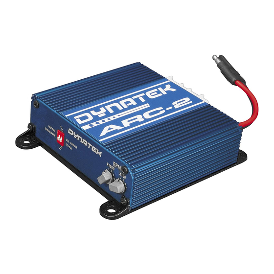
DYNATEK ARC-2 Manual - Page 8
Browse online or download pdf Manual for Motorcycle Accessories DYNATEK ARC-2. DYNATEK ARC-2 10 pages.

Standard Installation Diagrams (CONTINUED):
Note: Perform all cuts and splices close to the coil. There should be NOTHING ELSE connected to the
wires that go between the ARC-2 and coil (the white, blue, and black wires). Failure to follow this will likely
damage anything else connected, and possibly damage the ARC-2 and coil as well.
Typical 4 cylinder Distributorless Ignition, 2-coil setup with Integrated Drivers (Ex: Evo8):
*** CANNOT USE COILS WITH
INTEGRATED DRIVER IN A CDI
APPLICATION (SEE TEXT) ***
ECU or Power Transistor
BEFORE
AFTER
ECU or Power Transistor
ARC-2
*** ARC-2 DIP SWITCH SHOULD BE SET
FOR COIL WITH DRIVER INPUT ***
SWITCHED +12V
SPLICE
CUT
SWITCHED +12V
SPLICE
CUT
SPLICE
CUT
RED 12GA
30A FUSE
BLACK 12GA
-
BATTERY
ARC-2
Coil for
cylinders 1 and 4
ground
Coil for
cylinders 2 and 3
ground
Coil for
cylinders 1 and 4
*** MUST SUBSTITUTE ORIGINAL
INTEGRATED DRIVER COILS WITH CDI
COMPATIBE COILS (SEE TEXT) ***
Coil for
cylinders 2 and 3
+
Asynchronous Restriking CDI
2801211
- 8
