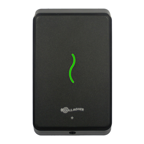
Gallagher T11 Installation Note - Page 3
Browse online or download pdf Installation Note for Card Reader Gallagher T11. Gallagher T11 11 pages.
Also for Gallagher T11: Installation Note (11 pages), Installation Note (13 pages)

Installa on Note
* The matching of wire sizes to equivalent wire gauges are only approximate.
Grounding shielded cable may reduce the obtainable cable length by 25% to 30%.
Distance between Proximity Readers
The distance separa ng any two proximity readers must not be less than 200 mm
(8 inches) in all direc ons.
When moun ng a proximity reader on an internal wall, check that any reader fi xed
to the other side of the wall is not less than 200 mm (8 inches) away.
Installa on
The Gallagher T11 Reader is designed to be mounted on ver cally orientated
electrical fl ush (gang) boxes, or any solid fl at surface. However installa on on metal
surfaces, par cularly those with a large surface area will reduce read range. The
extent to which the range is reduced will depend upon the type of metal used.
The recommended moun ng height for the reader is 1.1 m (3.6 ) from the fl oor
level to the centre of the reader device. However this may vary in some countries
and you should check local regula ons for varia ons to this height.
1.
Ensure the building cable has been run out through the fl ush box.
If you are not moun ng to a fl ush box, use the drill template at the back of this
installa on note as a guide, to drill all fi ve holes. Drill the 13 mm (1/2 inch)
diameter centre hole (this is the centre hole for which the building cable will
exit the moun ng surface) and the four fi xing holes.
2.
Run the building cabling through the reader base.
3.
Secure the base to the fl ush box using the two 6-32 UNC screws provided. It is
important the base of the reader is fl ush with and ght against the moun ng
surface.
Part Number: 3E2513 | Edi on 10
November 2012
200 mm
Gallagher T11 Reader
Page 3
