adeptus 78105 Assembly Instructions Manual - Page 10
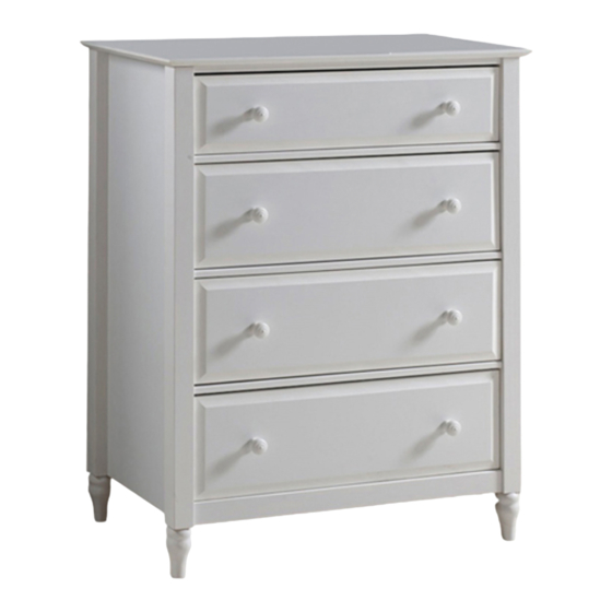
Browse online or download pdf Assembly Instructions Manual for Indoor Furnishing adeptus 78105. adeptus 78105 14 pages. Cottage 4 drawer chest
Also for adeptus 78105: Assembly Instruction Manual (14 pages), Assembly Instruction Manual (14 pages)

11
ASSEMBLE THE LARGE DRAWERS (3X)
11
2x B
A
A
10
STEP 13 - C
• Align the groove in the drawer back (part
13) with the drawer bottom (part 14) and in
between the drawer sides (parts 11 & 12).
• Secure the drawer back (part 13) to the
drawer using 2 screws (part B) on each
side, as shown.
B
B
11
B
14
G
10
10
G
3
• Attach the knobs (part G) to the drawer
front (part 10) by inserting the screw
(part B) through the back of the drawer
front (part 10) and into the back of the
knob (part G).
NOTICE: THE WRITTEN INSTRUCTIONS CONTAINED HEREIN ARE COPYRIGHTED.
B=30
G=06
4 x 30
mm
Screw
STEP 13 - A
• Using the dowels (part A) inserted into parts 11 and 12 in step 1, align the
drawer sides (parts 11 & 12) with the drawer front (part 10).
• Make sure the groove for the drawer bottom (part 14) is precisely aligned
on all 3 parts (10, 11 & 12) then push together until flush.
• Secure the drawer sides (parts 11 & 12) to the drawer front (part 10) using
12
2 screws (part B) on each side as shown in the illustration.
B
• Screws (part B) should be tight, but do not force or over-tighten as this
B
could cause the wood to split.
A
A
11
13
B
B
B
12
STEP 13 - E
With the drawer upside down,
E=03
(
E)
300
Knob
STEP 13 - B
14
12
10
D
D
• Align the left drawer runner (
toward the drawer back (part 13). Make sure the opposite end is all
the way forward touching the drawer front (part 10), as shown.
• Secure the left drawer runner (
11) using 3 screws (part D).
• The first screw (part D) goes through the 3rd hole back from the drawer
front (part 10) and into the left drawer side (part 11).
• The second screw (part D) goes through the center hole of the runner
(
E) (part E) into the left drawer side (part 11).
300
• The third screw (part D) goes through the last hole in the runner (
(part E) closest to the drawer back (part 13) on the outside by the wheel
as shown.
• Repeat these steps to attach the (
the right drawer side (part 12).
F=03
(
D)
300
Right
Left
Drawer
Drawer
Runner
Runner
• Slide the drawer bottom (part 14) into
the grooves on parts 10, 11 and 12 as
shown
D
F
13
14
D E
10
D
11
E) (part E) with the wheel on the outside
300
E) (part E) to the left drawer side (part
300
D) right drawer runner (part F) to
300
D=18
3.5 x 14
mm
Screw
(
E)
300
D
E)
300
10 14
