Gallien-Krueger 800RB Operating Instructions - Page 2
Browse online or download pdf Operating Instructions for Amplifier Gallien-Krueger 800RB. Gallien-Krueger 800RB 4 pages. Gallien-krueger 800rb: user guide
Operating Instructions
800RB
The Basics
Your new GK 800RB Bass Amplifier represents the latest
advances that technology has to offer. Contained in a small
lightweight package are a set of unbeatable voicing filters, a
four-band equalizer, a tunable electronic crossover and a bi-amp
power amplifier. When used properly, these features will give
you the most exciting bass sound available today. A careful
examination of this manual will help you understand how to take
full advantage of its capabilities.
Block Diagram
Input Section
This section contains the 1/4'' input jack and the input attenuator.
With the attenuator out, the maximum input level is 1V rms (3V
P-P). For larger input signals, the input attenuator should be set.
This reduces the gain of the input stage by 10dB, increasing the
input head room to 3V rms (10V P-P).
Effects Loop
Located on the rear panel, it is provided for the insertion of out-
board effects. It is post EQ but pre Boost and Master. Using
standard guitar cords, connect the effects input to the send and
the effects output to the return. The Boost and Master controls
will not effect any signal put into the return jack. The level is
1.5V rms (4.5V P-P) into 100K ohm.
Direct Out
This is an electronically balanced output that will put 500mv rms
into a 600 ohm load. It comes after the effects loop and is located on
the rear panel.
Speakers
Located on the rear panel are two sets of speaker jacks. The
upper set is for the 100W power amp and in the bi-amp mode is
used for the high end. They deliver 100W rms into 8 ohms.
Lower impedances should not be used. Higher impedances such
as 8 ohms or above are okay.
CAUTION : Under no circumstances should the 100W and
300W outputs be connected together or to the same speaker!
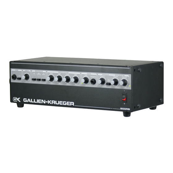
Power Switch
The Power Switch and associated LED indicator are located in
the lower right hand corner of the front panel
Fuse
Located on the rear panel, never operate this amplifier with any
other than the recommended fuse :
115V operation - replace with Type 3AG7A
230V operation - replace with Type 3AG4A
Power Cord
The Power Cord is detachable and plugs into the rear panel sock-
et. If a replacement is used it should be UL rated for 10A, 125V
operation. If using 240V, the cord should be UL rated for 240V,
5A operation.
Maintenance
Your new amplifier is rugged. It was built to give you a lifetime
of trouble-free operation. If it is operated in accordance with the