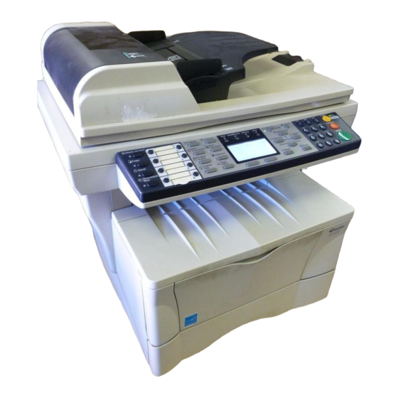
Copystar CS-1820 Service Manual - Page 4
Browse online or download pdf Service Manual for Copier Copystar CS-1820. Copystar CS-1820 14 pages.
Also for Copystar CS-1820: User Manual (4 pages)

1-6-13 Removing the exposure lamp ............................................................................................................ 1-6-34
1-6-14 Removing the scanner mirror A ......................................................................................................... 1-6-36
1-6-15 Removing the scanner motor ............................................................................................................. 1-6-37
1-6-16 Removing the main charger unit ........................................................................................................ 1-6-40
1-6-17 Adjustment the maintenance mode .................................................................................................... 1-6-41
(1) Adjusting the leading edge registration of image printing ............................................................. 1-6-41
(2) Adjusting the center line of image printing .................................................................................... 1-6-42
(3) Adjusting the amount of slack in the paper ................................................................................... 1-6-43
(4) Adjusting magnification of the scanner in the main scanning direction ........................................ 1-6-44
(5) Adjusting magnification of the scanner in the auxiliary scanning direction ................................... 1-6-45
(6) Adjusting the scanner leading edge registration ........................................................................... 1-6-46
(7) Adjusting the scanner center line ................................................................................................. 1-6-47
(8) Adjusting the margins for scanning an original on the contact glass ............................................ 1-6-48
(9) Adjusting the DP magnification ..................................................................................................... 1-6-49
(10) Adjusting the DP leading edge registration .................................................................................. 1-6-50
(11) Adjusting the DP trailing edge registration ................................................................................... 1-6-51
(12) Adjusting the DP center line ......................................................................................................... 1-6-52
(13) Adjusting the margins for scanning the original from the DP ........................................................ 1-6-53
1-7 Upgrading the firmware
1-7-1 Upgrading the firmware on the main PWB ........................................................................................... 1-7-1
2-1 Mechanical construction
2-1-1 Paper feeding system .......................................................................................................................... 2-1-1
(1) Paper feed control .......................................................................................................................... 2-1-2
(2) Paper feeding mechanism .............................................................................................................. 2-1-3
2-1-2 Original scanning system ..................................................................................................................... 2-1-4
(1) ISU unit ........................................................................................................................................... 2-1-6
2-1-3 Electrophotographic system ................................................................................................................. 2-1-7
(1) Electrophotographic cycle .............................................................................................................. 2-1-7
(1-1) Process unit mechanism ....................................................................................................... 2-1-8
(2) Main charging ................................................................................................................................. 2-1-9
(2-1) Photo conductive drum .......................................................................................................... 2-1-9
(2-2) Charging the drum ............................................................................................................... 2-1-10
(3) Exposure ...................................................................................................................................... 2-1-11
(3-1) Laser scanner unit ............................................................................................................... 2-1-12
(3-2) Drum surface potential ........................................................................................................ 2-1-13
(4) Development ................................................................................................................................ 2-1-14
(5) Transfer ........................................................................................................................................ 2-1-15
(6) Fusing ........................................................................................................................................... 2-1-16
(6-1) Fuser unit mechanism ......................................................................................................... 2-1-17
(7) Cleaning ....................................................................................................................................... 2-1-18
2-2 Electrical Parts Layout
2-2-1 Electrical parts layout ........................................................................................................................... 2-2-1
(1) Main unit ......................................................................................................................................... 2-2-1
(2) Scanner unit ................................................................................................................................... 2-2-2
2-3 Operation of the PWBs
2-3-1 Main PWB ............................................................................................................................................ 2-3-1
2-3-2 Engine PWB ......................................................................................................................................... 2-3-7
(1) Eraser lamp control circuit .............................................................................................................. 2-3-9
(2) Heater lamp control circuit ............................................................................................................ 2-3-10
(3) Polygon motor control circuit ........................................................................................................ 2-3-13
2-3-3 Power supply PWB ............................................................................................................................ 2-3-17
2-3-4 Bias PWB ........................................................................................................................................... 2-3-19
2-3-5 High voltage PWB .............................................................................................................................. 2-3-20
(1) Interlock switch ............................................................................................................................. 2-3-21
2GM
