Galls ST160 SIREN Installation And Operating Instructions Manual - Page 3
Browse online or download pdf Installation And Operating Instructions Manual for Amplifier Galls ST160 SIREN. Galls ST160 SIREN 7 pages. Siren amplifier
Also for Galls ST160 SIREN: Installation And Operating Instructions Manual (12 pages)
SPECIFICATIONS
Input Voltage
10 - 16 VDC (negative ground)
Input Current
8.0 Amps @ 13.6 VDC (single 100W speaker)
Standby Current
Less than 150 mA
Audio Frequency
200Hz - 10 kHz + 3db
Audio Output
40 watts @13.6 VDC
Output Power
105 WATTS RMS MAX. (15.0 VDC - single 100W speaker)
Siren Frequency
675Hz - 1633Hz
High Voltage Protection
16 - 18 VDC will cause siren output to cease, resumes at normal voltage
Short Circuit Current
50 AMPS (supply circuit must be capable of supplying this)
Operating Temperature
-15° F to +140°F
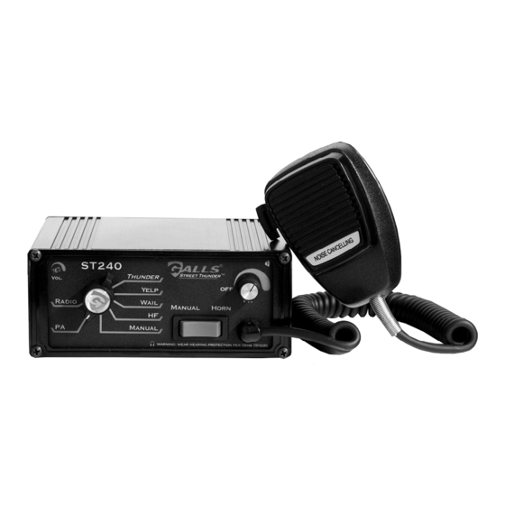
Controls
7-position rotary switch (Radio, PA, Manual, HF, Wail, Yelp, Thunder)
Momentary Manual/Horn rocker switch
Auxiliary input (jumper programmable) for positive or negative horn
-Remote Manual or Hands Free operation
Park Kill input (jumper programmable) for positive or negative activation
Thunder (and Two-Tone) disable (jumper programmable)
Two-Tone activation (swaps modes with Thunder) (jumper programmable)
Connections
Detachable, 12-pin, positive locking connector with pigtail leads.
(12-Pin Connector)
(1) Positive, (1) Negative, (1) Activation (on/off), (1) Backlighting,
(2) Speaker, (2) Radio, Auxiliary, Park Kill
Size
6" Wide, 6 -1/2" Deep, 2 -1/2" High
Shipping Weight
6 lbs.
LIMITED WARRANTY
Galls warrants this new product to be free from defects in material and workmanship, under
normal use and service, for a period of seven (7) years from the date of delivery to the first
user-purchaser.
During this warranty period the obligation of Galls is limited to repairing or replacing, as
Galls may elect, any part or parts of such product which after examination by the
manufacturer is determined to be defective in material and/or workmanship.
This warranty does not cover labor charges for removal or re-installation of the product.
Fuses and lamps are not covered under this warranty.
This warranty does not extend to any unit that has been subjected to abuse, misuse, improper
installation or which has not been adequately maintained, nor to units which have problems
related to service or modification at any facility other than the manufacturer.
THERE ARE NO OTHER WARRANTIES, EXPRESSED OR IMPLIED, INCLUDING BUT
NOT LIMITED TO, ANY IMPLIED WARRANTIES OF MERCHANTABILITY OR FITNESS
FOR A PARTICULAR PURPOSE. IN NO EVENT SHALL GALLS AND/OR THE
MANUFACTURER BE LIABLE FOR ANY LOSS OF PROFITS OR ANY INDIRECT OR
CONSEQUENTIAL DAMAGES ARISING OUT OF ANY SUCH DEFECT IN MATERIALS
OR WORKMANSHIP.
-11-
INSTALLATION
Proper installation of the unit is essential for years of safe, reliable operation.
Please read all instruction before installing the unit. Failure to follow these
instructions can cause serious damage to the unit or vehicle and may void
warranties.
Qualifications - The installer must have a firm knowledge of basic electricity,
vehicle electrical systems and emergency equipment.
Keep These Instructions - Keep these instructions in the vehicle or other safe place
for future reference. Advise the vehicle operator of the location.
Unpacking - Inspect contents for shipping damage. If found, alert carrier
immediately. Contents should include unit with microphone, mounting bracket w/ 2
bolts, microphone bracket with 2 screws, wiring harness with connector, and these
instructions. Contact your supplier immediately if any components are missing.
Installer Selectable Options (Jumper Settings)
The ST160 has several options that can be selected during installation. Jumpers on
the printed circuit board, inside the case, allow the installer to select these various
options. These options should be set before installation of the unit.
Cover Removal - Remove the four Philip head screws located on the back of the
unit. DO NOT REMOVE THE SCREWS ON THE FRONT OF THE UNIT! Slide
the top cover back and away from the front face of the unit. This cover can be
removed completely from the siren unit. CAUTION!!! DO NOT OVER-TIGHTEN
SCREWS.
After the cover has been removed, find the location of the option jumpers (see
diagram below).
-2-