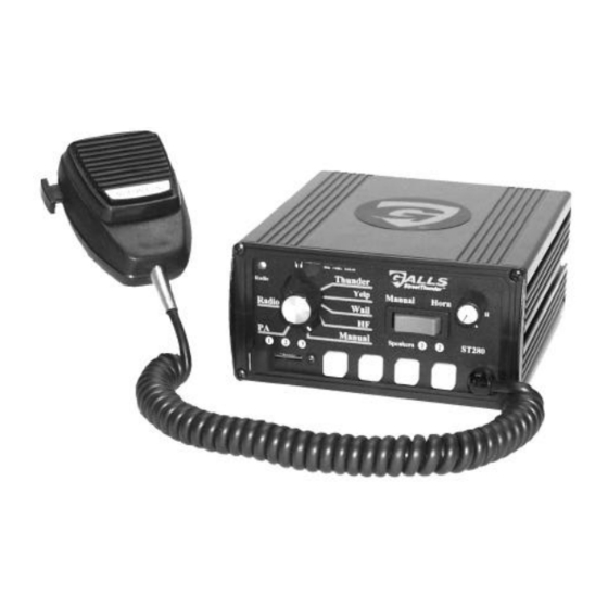
Galls Street Thunder ST280 Installation And Operating Instructions Manual - Page 7
Browse online or download pdf Installation And Operating Instructions Manual for Amplifier Galls Street Thunder ST280. Galls Street Thunder ST280 18 pages. Siren amplifier & light controller
Also for Galls Street Thunder ST280: Installation And Operating Instructions Manual (20 pages)

Please follow these guidelines when wiring the siren:
• Use only high quality crimp connectors.
• Make sure all connections are tight.
• Route wiring to prevent wear, overheating and interference with air bag
deployment.
• Use grommets and sealant when passing through compartment walls.
• Minimize the number of splices to reduce voltage drop.
• Ground connections should only be made to substantial chassis components,
preferably directly to the negative of the vehicle battery.
• Install and check all wiring before connection to vehicle battery.
Siren Wiring Connections:
Siren input and output connections are made on the back of the unit through a
12-pin connector and wiring harness.
3
2
1
6 5 4
9
8
7
12 11 10
Please review the Siren Wiring diagram on page 8 and make your connections
as follows:
BLACK: (Pins 2 & 5) Ground - Connect these leads to the negative of the
battery, or to a good chassis ground. You MUST connect both
leads if you are using two 100-watt speakers. Be sure to use
minimum size #14 AWG wire.
RED: (Pins 1 & 4) Power - Connect both leads to the positive side of the
battery, or to a high current power buss. You MUST connect both
leads if you are using two 100-watt speakers. A power relay may
also be used. Be sure to use minimum size #14 AWG wire.
YELLOW: (Pin 11) Ignition Switched Power - Connect to +12VDC through
a switched power supply (possibly ignition). This will turn the
siren on and off. Be sure to use minimum size #18 AWG wire.
ORANGE: (Pin 9) Backlight Power - This lead supplies power for the
backlighting of the siren. Connect it to +12VDC from the dash
lights, parking lights or other switched source. Be sure to use
minimum size #18 AWG wire.
BROWN: (Pins 7 & 12) Speaker Output - Connect one lead to each terminal
or lead of the speaker. Be sure to use minimum size #14 AWG
wire. If connecting a second speaker in parallel, you must
observe the polarity of the speakers (phasing). Be sure that the
positive terminals of both speakers are connected together to the
same brown wire from the siren. In which case, the negative
terminals of both speakers would also be connected together to the
other brown wire.
-6-
