AGS Merlin 1500S User & Installation Manual - Page 3
Browse online or download pdf User & Installation Manual for Control Panel AGS Merlin 1500S. AGS Merlin 1500S 8 pages. Gas & ventilation interlock system
Also for AGS Merlin 1500S: Installation & Operation Manual (12 pages), User Manual (12 pages)

Merlin 1500S
Gas Interlock System
1
General Information
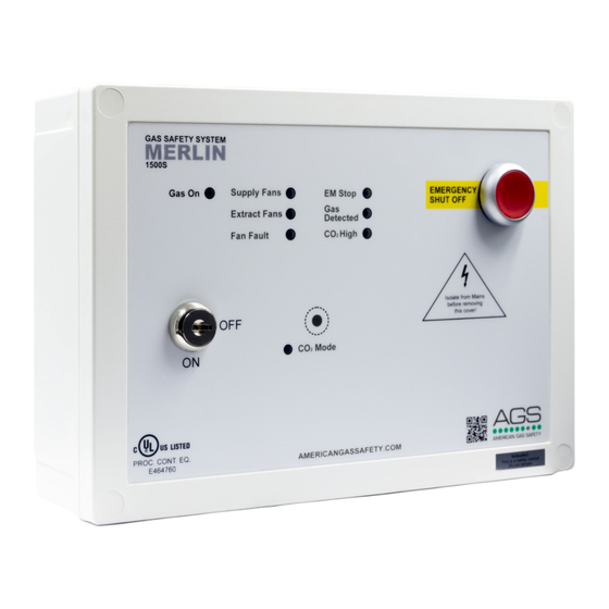
The Merlin 1500S is a ventilation interlock panel.
The Merlin 1500S can receive connections from up to four external remote air pressure
differential switches or current monitors, remote emergency shut-off buttons, gas detectors and
a Merlin CO
monitor. It can also be integrated with a BMS and fire alarm.
2
It is recommended that the user reads this guide before using the system. Please do NOT
attempt to operate the unit until the contents of this document have been read and are
thoroughly understood.
2
Installation
2.1
Panel Mounting. The control panel is designed for surface mounting using 4 mounting
screws. Removing the cover on the panel gives access to the circuit board. The PCB should be
removed before drilling entry holes into the case.
2.2
Mains Supply. A 110-120VAC electrical supply should be supplied to the panel. This
should be externally fused at 3 Amps using a fused spur and should be connected to the
terminals marked [LNE Power].
2.3
Gas solenoid valve. The gas solenoid valve should be powered using the terminals on the
Merlin 1500S marked [LNE GAS VALVE].
2.4
Supply Fan & Extract Fan PD Switches These terminals are used to receive an input signal
from external air pressure switches or external current monitors. These are linked out as a factory
setting. Wiring should be made using two-core volt free connections. If only one fan is being
used the terminals not in use should be left linked out.
2.5
BMS Connections Terminal connections are available on the circuit board for
connections to Building Management systems etc. Detailed on the circuit board as [BMS OUT
N/C, Com and N/O] these are volt free connections.
2.6
Remote emergency shut off buttons. The terminal for remote emergency shut-off buttons
is detailed on the circuit board as [EM REMOTE]. These connections are linked out as a factory
setting. Remote emergency shut-off buttons should be volt free and wired to the Merlin 1500S
using two-core cable.
2.7
Gas Detector The terminals detailed on the circuit board as "Gas Detector". These
+ -
connections are [
used leave the link in between the "
2.8
FS 123 This terminal switches when the key is turned on and off. This can be linked to a fan
switch (panel supplied separately) which can provide power to the fans when the control panel
is switched on.
2.9
CO2 Monitor This terminal can be wired to CO2 monitor to shut off the system in the event
of CO2 being at alarm level. If no CO2 monitor is supplied leave the terminal link in.
2.10
12v DC This is a permanent 12v DC output when there is power at the panel. This is
normally used to power a PM2 current monitor. (Supplied separately)
2.11
Internal Buzzer Operates at 65dB measured 30cm from closed panel.
Note: all low voltage connections should be made using a screened cable. To avoid electrical interference
this should not be in the same conduit as mains cable as per the low voltage directive.
Rev: 03 Date: 08-01-18
] these can be wired to a Merlin gas detector. If no detector is being
".
User & Installation Manual
3
