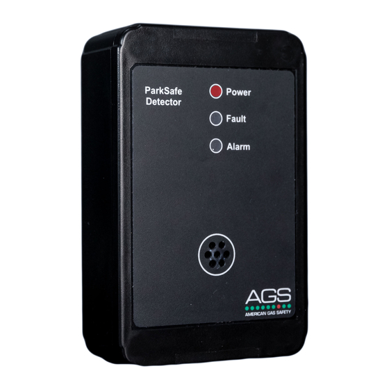
AGS Parksafe Control Panel Installation, Operation & Maintenance Manual - Page 4
Browse online or download pdf Installation, Operation & Maintenance Manual for Control Panel AGS Parksafe Control Panel. AGS Parksafe Control Panel 20 pages. Ventilation control panel
Also for AGS Parksafe Control Panel: Installation & Operation Manual (16 pages), Installation & Operation Manual (16 pages), Installation Operation & Maintenance (16 pages)

Installation, Operation & Maintenance
Installation
Typical Application & Location
Refer to your PARKSAFE Detector manual for important information regarding coverage, location and positioning including areas
and conditions to avoid!
Installation must be in accordance with recognised standards in the country concerned, for North America, NEC / CEC regulations
should be followed!
Access to the interior of the controller, when carrying out any work, must only be conducted by trained personnel!
Before carrying out any work ensure local regulations and site procedures are followed!
The use of sound strobes is highly recommended!
Consult with local codes for the specific requirements!
In parking structures, CO and NO2 are two of the most abundant airborne contaminants and poses significant
safety concerns. The CO and NO2 levels must be controlled or ventilated when concentrations approach
hazardous levels. The controller is designed for installation into car parking facilities and enclosed garages
paired with AGS ParkSafe detectors (Nitrogen Dioxide and Carbon Monoxide) that will be linked via Modbus
RTU protocol back to the controller and monitor the detectors in numbers up to 16 (per controller) and
automatically control ventilation systems according to gas levels and an optional temperature level. The
ParkSafe controller monitoring system can activate both the exhaust fan(s) and the air intake device(s) such as
outside air louvers/dampers and make up air units
The ParkSafe will make or break a dry contact internally on relay terminals [Output-1] and a second contact on
[Output-2]. This is to have a live feed to the ventilation system wired through the contact so that the ParkSafe
can activate ventilation systems; this can be either via a direct live feed or via a run signal. Another output relay
will energise after [Output-2] has been active for an extended period. This is used for a link to a BMS or other
external indication device. The controller also has a 0-10vdc output to allow the controller to drive VFD's based
on gas level outputs.
Addressable AGS ParkSafe detectors are daisy-chained through a RS485 RTU communication protocol to the
controller. The controller must be located out of reach of the public, preferably located inside, close to the
motor control centre or in connecting offices. Place the controller in accordance with applicable regulations.
Easy accessibility is recommended for both status observation and alarm purposes.
Rev: 20
ParkSafe Controller
4
