Maintronic AV32 Quick Manual - Page 2
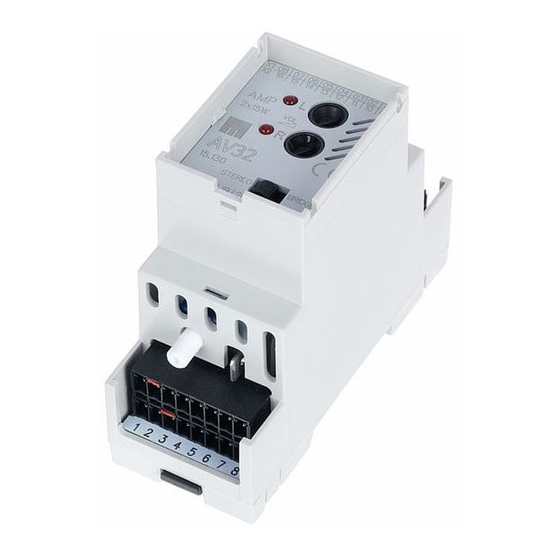
Browse online or download pdf Quick Manual for Amplifier Maintronic AV32. Maintronic AV32 4 pages. Stereo audio endstufe

1
Signal LED CH. links
signal LED CH. left
2
Lautstärkeregler links
volume control left channel
3
Lautstärkeregler rechts
volume control right channel
4
Signal LED CH. rechts
signal LED CH. right
Bridge Mode Schalter
bridge mode switch
5
(Signaleinspeisung IN1)
(signal entry IN 1)
Anschlüsse oben / terminal top
-X1
01
Spannung + 24V DC
02
Spannung + 24V DC
03
Masse GND
04
Masse GND
05
Lautsprecher -
06
Lautsprecher -
07
Lautsprecher + rechts
08
Lautsprecher + links
Spannungsversorgung - 24 Volt Gleichspannung
Die Spannungsversorgung benötigt eine Gleichspannung mit
24 Volt. Es sind jeweils 2 Klemmen vorhanden, die zum Durch-
schleifen verwendet werden können (Pin 01 ... 04).
Power supply - 24 Volt DC
The power supply needs a direct current voltage of 24 Volt.
Two pins are available for loop trough (Pin 01 ... 04).
Lautsprecher Anschlüsse
Lautsprecher mit einer Impedanz von 4 Ohm oder 8 Ohm
können angeschlossen werden. Im Bridged Betrieb dürfen
nur Lautsprecher mit einer Impedanz von 8 Ohm verwendet
werden und der Schalter (5) muss auf Bridge stehen.
Loudspeaker connectors
You can use loudspeakers with an impedance of 4 Ohms or
8 Ohms at the audio outputs. The loudspeakers can be oper-
ated in stereo and also bridged mode (see the terminal assign-
ment in the circuit layout). Loudspeakers with an impedance of
8 Ohms are required when operating in bridged mode (make
sure that the switch is set to bridge).
4
DC power + 24V DC
DC power + 24V DC
Power Ground
Power Ground
Speaker out -
Speaker out -
Speaker out + right
Speaker out + left
5
-X2
09
Mikro Eingang aktivieren
microphone enable
10
Input 1 aktivieren
input 1 enable
11
Input 2 aktivieren
input 2 enable
12
Input 3 aktivieren
input 3 enable
13
Input 4 aktivieren
input 4 enable
H/L Aktiv - Input invertieren
H/L active invert input high
14
high oder low
or low
15
Spannung + 24V DC
DC power + 24V DC
16
Masse GND
Power Ground
Pin 09-13 - Mikro- und Audio Eingänge 1-4
Mikro- und Audio Inputs 1 bis 4 können extern aktiviert oder
abgeschalten werden. Dazu wird eine 24VDC Spannung an den
jeweiligen Pin angelegt.
Pin 14 - H/L aktiv - Standard ist low aktiv - es werden 24V benö-
tigt um die Eingänge einzuschalten . Mit einer Brücke von Pin
15 auf Pin 14 werden alle Eingänge auf High aktiv geschalten.
High aktiv bedeutet, es wird eine 24VDC Spannung an den Ein-
gang angelegt um abzuschalten.
Pin 09-13 - Micro- and Audio IN 1-4
The microphone and the audio IN 1-4 can be activated and
deactivated externally. Therefor a 24V DC power connected to
the respective pin is necessary.
Pin 14 - H/L active - The inputs are low active by default - a
24VDC Power is necessary to activate the inputs. All inputs are
switched to high active with the help of a bridge from pin 15 to
pin 14. High active means, a 24V DC power must be connected
to the inputs to deactivate them.
6
