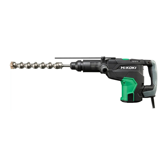
HIKOKI DH 52MA Handling Instructions Manual - Page 12
Browse online or download pdf Handling Instructions Manual for Impact Driver HIKOKI DH 52MA. HIKOKI DH 52MA 16 pages.

2. Inspecting the mounting screws
Regularly inspect all mounting screws and ensure that
they are properly tightened. Should any of the screws be
loose, retighten them immediately. Failure to do so could
result in serious hazard.
3. Maintenance of the motor
The motor unit winding is the very "heart" of the power
tool.
Exercise due care to ensure the winding does not
become damaged and/or wet with oil or water.
4. Inspecting the carbon brushes (Fig. 15)
The Motor employs carbon brushes which are
consumable parts. When they become worn to or near
the "wear limit" ⓐ, it results in motor trouble.
When an auto-stop carbon brush is equipped, the motor
will stop automatically. At that time, replace both carbon
brushes with new ones which have the same carbon
brush Numbers ⓑ shown in the Fig. 15. In addition,
always keep carbon brushes clean and ensure that they
slide freely within the brush holders.
5. Replacing carbon brushes (Fig. 15)
Loosen the two set screws and remove the tail cover.
Remove the brush caps and carbon brushes. After
replacing the carbon brushes, do not forget to tighten the
brush caps securely and to install the tail cover.
6. Replacing supply cord
If the replacement of the supply cord is necessary, this
has to be done by the manufacturer of this agent in order
to avoid a safety hazard.
CAUTION
In the operation and maintenance of power tools, the
safety regulations and standards prescribed in each
country must be observed.
GUARANTEE
We guarantee HiKOKI Power Tools in accordance with
statutory/country specifi c regulation. This guarantee does
not cover defects or damage due to misuse, abuse, or
normal wear and tear. In case of complaint, please send
the Power Tool, undismantled, with the GUARANTEE
CERTIFICATE found at the end of this Handling instruction,
to a HiKOKI Authorized Service Center.
IMPORTANT
Correct connection of the plug
The wires of the main lead are coloured in accordance
with the following code:
Blue: — Neutral
Brown: — Live
As the colours of the wires in the main lead of this tool may
not correspond with the coloured markings identifying the
terminals in your plug proceed as follows:
The wire coloured blue must be connected to the terminal
marked with the letter N or coloured black. The wire
coloured brown must be connected to the terminal marked
with the letter L or coloured red. Neither core must be
connected to the earth terminal.
NOTE:
This requirement is provided according to BRITISH
STANDARD 2769: 1984.
Therefore, the letter code and colour code may not be
applicable to other markets except The United Kingdom.
Information concerning airborne noise and vibration
The measured values were determined according to
EN62841 and declared in accordance with ISO 4871.
Measured A-weighted sound power level: 108 dB (A)
Measured A-weighted sound pressure level: 97 dB (A)
Uncertainty K: 3 dB (A).
Wear hearing protection.
Vibration total values (triax vector sum) determined
according to EN62841.
Hammer drilling into concrete:
Vibration emission value
Uncertainty K = 1.5 m/s
Equivalent chiselling value:
Vibration emission value
Uncertainty K = 1.5 m/s
The declared vibration total value and the declared noise
emission value have been measured in accordance with a
standard test method and may be used for comparing one
tool with another.
They may also be used in a preliminary assessment of
exposure.
WARNING
○ The vibration and noise emission during actual use
of the power tool can diff er from the declared total
value depending on the ways in which the tool is used
especially what kind of workpiece is processed; and
○ Identify safety measures to protect the operator that
are based on an estimation of exposure in the actual
conditions of use (taking account of all parts of the
operating cycle such as the times when the tool is
switched off and when it is running idle in addition to the
trigger time).
NOTE
Due to HiKOKI's continuing program of research and
development, the specifi cations herein are subject to
change without prior notice.
Information for power supply system to be used with
electric tools provided with rated voltage 230 V~
Switching operations of electric apparatus cause voltage
fl uctuations.
The operation of this electric tool under unfavorable mains
conditions can have adverse eff ects to the operation of other
electric apparatus.
With a mains impedance equal or less than 0.327 Ohms
there will probably be no negative eff ects.
Usually, the maximum permissible mains impedance will
not be exceeded when the branch to the power outlet is fed
from a junction box with a service capacity of 25 ampere or
higher.
In case of power failure, or when the power plug is pulled
out, immediately return the switch to OFF position. This
prevents an uncontrolled restart.
12
a
h , HD = 15.1 m/s
2
2
a
h , CHeq = 10.8 m/s
2
2
