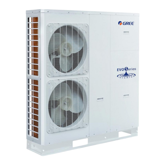
Gree HLR8Pd/Na-K Unit Installation Manual - Page 8
Browse online or download pdf Unit Installation Manual for Chiller Gree HLR8Pd/Na-K. Gree HLR8Pd/Na-K 18 pages. Mini chiller

Unit Installation
Wiring of the tank-type electric heater is the same as that stated above.
◆
1L1
3L2
13
NC
NO
14
22
NO
NC
2T1
4T26
AC Contactor 1
1L1
3L2
21
13
NO
NC
14
22
NO
NC
2T1
4T26
AC Contactor 2
Notes:
During installation, the electric heater should be supplied with three-phase power separately. When only
①
one group of the electric heater is installed, please follow the wiring of any group of the diagram shown above.
Quantity of the AC contactors should match with that of the electric heater installed. Proper AC
②
contactors which meet the actual demands should be adopted.
The wiring mode depends on if the tank-type electric heater is equipped with a thermostat or not.
③
Proper power lines should be used and those that do not meet actual demands should be avoided.
④
Never open the electric box for wiring of the mainboard by the user themselves.
⑤
4.2 Pre-Installation
(1). Installation of the unit must be in accordance with national and local safety codes.
(2). Installation quality will directly affect the normal use of the air conditioner unit. The user is prohibited
from installation by himself. Please contact your dealer after buying this machine.Professional installation
workers will provide installation and test services according to the installation manual.
(3). Do not connect to power supply until all installation work is completed.
4.3 Selection of Installation Location
(1). The monobloc unit must be installed on a firm and solid support.
(2). Avoid placing the monobloc unit under window or between two constructions, hence to prevent normal
operating noise from entering the room.
(3). Air flow at inlet and outlet shall not be blocked.
(4). Install at a well-ventilated place, so that the machine can absorb and discharge sufficient air.
(5). Do not install at a place where flammable or explosive goods exist or a place subject to severe dust,
salty fog and polluted air.
Field Instalaltion Diagram of the Electric Heater
5L3
21
A1
A2
T3
5L3
A1
A2
T3
9
(without the thermostat)
Electric Box
6
6
7
7
8
8
Wiring Board
34
34
35
35
36
36
XT2
6
X17
X18
Mainboard AP1
CN26
CN27
