Centro PoE-2010-8E Quick Start Manual - Page 3
Browse online or download pdf Quick Start Manual for Network Router Centro PoE-2010-8E. Centro PoE-2010-8E 3 pages. Unmanaged fast-ethernet switch with poe injector
-
Installation steps:
Please check the following items before installation, if t is missing ,please contact the dealer.
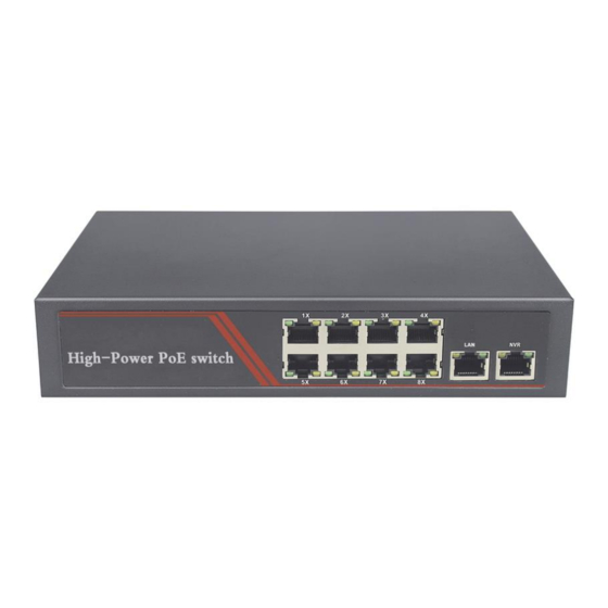
10 ports PoE Ethernet Switch
Ac power cable
Accessory
User manual
Please follow the below installation steps
1.)Please turn off the signal power and display device power before installation, installation with power will
damage the transmission equipment;
3.)Use network cable connect PoE IP camera and 1~8 downlink ports of product respectively
4.)Use a network cable connect equipment up link port and NVR or computer Connect power adapter
5.)Check if the installation is correct equipment is in good condition the connection is stable then provide power for system
6.)Ensure the Ethernet equipment with power and work properly.
Trouble Shooting
Please follow the steps if the equipment has tro. uble
(1).Make sure the equipment is installed according to the manufactures installation guide
(2).Conf RJ45 cable order meets EIA/TIA568A or 568B standard.
(3).Every PoE port can provide PoE equipment maximum power less than 30W, please do not connect the PoE
equipment with power over 30W
(4).Replace the equipment with a proper functioning 8 ports PoE Ethernet Switch to check if the equipment is
damage.
(5).Please contact your vendor if trouble still e.xist.
Plug Producing Method
Instruments to be used: wire crimper, network tester. Wire sequence of RJ45 plug should conform
with EIA/TIA568A or 568B.
(1).Please remove 2cm long the insulating layer and bare 8 pairs UTP cable
(2).Separate the 8 pairs UTP cable and straighten them
(3).Line up the 8 pieces of cables per EIA TIA 568A or 568B
(4).Cut off the cables to leave 1.5cm bare wire
(5).Plug 8 cables into RJ45 plug make sure each cable is in each pin
(6).Use the wire crimper to crimp it
(7).Repeat above 9 steps to make the another end
(8).Use network tester to test the cable if t works
Pin Color
/G
1
White
reen
Green
2
3 White/Orange
4
Blue
/B
5
White
6
Orange
7 White/Brown
8
Brown
EIA/TIA 568A
Notice
When choose RJ45 make sure if one end is EIA/TIA568A,the other end should also be EIA/TIA568A.
When choose RJ45 make sure if one end is EIA/TIA568B,the other end should also be EIA/TIA568B.
lue
1pcs
1pcs
1pcs
1pcs
Pin
Color
1 White/Orange
2
Orange
3 White/Green
Blue
4
5
White/Blue
6
Green
7
White/Brown
8
Brown
EIA/TIA 568B