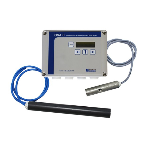
AFRISO OSA 3 Manual - Page 16
Browse online or download pdf Manual for Measuring Instruments AFRISO OSA 3. AFRISO OSA 3 20 pages. Level alarm for oil separator

Troubleshooting
Note:
If an input did not have a sensor
installed when the system was
installed, this will not be scanned.
To activate an inactive output, see
the Maintenance section.
Checks when alarms appear in the display
Problem
Layer alarm
"Level alarm act." alarm appears
in the display
"Sensor err on input 1 (level)" alarm
appears in the display
Damming alarm
"High level alarm act." alarm
"Sensor err on input 2 (high level)"
alarm appears in the display
Sludge alarm
"Sludge alarm act." alarm
"Sensor err on input 3 (sludge)"
alarm appears in the display
AFRISO EMA AB • Kilvägen 2, 232 37 Arlöv • Sweden • Phone +46-(0)40-92 20 50 • [email protected] • www.afriso.se
16
Note:
Check
Check the thickness of the oil/grease
layer
Measure voltage at sensor
Blockage at outlet to separator
(critical alarm)
Measure voltage at sensor
The sludge level has reached a set
alarm level (normal alarm)
Measure voltage at sensor
Seperator alarm OSA 3 • Manual
Sensors are activated in a se-
quence: Sensor 1 (level sensor
ES4 ) active in 4 sec -> sensor 2
(thermistor sensor R6-S) active in
45 sec -> sensor 3 (sludge sensor
ES8) active in 4 sec.This se-
quence is repeated continuously.
Cause/action
Order emptying
Error in sensor circuit to sensor (e.g.
cable failure/short-circuit)
Clear blockage or find out cause
Error in sensor circuit to sensor (e.g.
cable failure/short-circuit)
This normally means that the sludge
layer in the tank is too great, this
normally results in impairment of the
efficiency of the separator. Separator
emptying should be ordered.
Error in sensor circuit to sensor (e.g.
cable failure/short-circuit)
OSA 3
