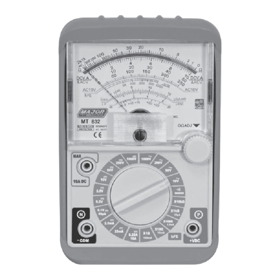
Major tech MT832 Instruction Manual - Page 8
Browse online or download pdf Instruction Manual for Multimeter Major tech MT832. Major tech MT832 12 pages. Analogue multimeter

4.1. RESISTANCE TEST
1. Set the function switch to the highest Ω
position.
2. Insert the test leads into COM (Black lead)
and "+" socket (Red lead)
3. Short the test leads and turn 0Ω adjusting
knob to set the pointer to zero position.
4. Make sure that there is no voltage across the
circuit to be tested.
5. Connect the test leads to the tested resistor
(Fig.01) and read the scale in accordance
with the reference table. Reset the function
switch to successively lower Ω positions to
obtain a higher resolution reading.
4.2. CONTINUITY TEST (BUZZ AND LED)
1. Plug the test leads into COM (Black lead) and "+" socket (Red lead)
2. Set the range function switch to BZ/CONT'Y position, apply the test
lead pins to two points to be tested. While tested circuit is continuous it
should indicate to you as below:
A. Buzz and LED lighting (ln on to 300),
B. Only the LED lighting (Up to 300).
WARNING: It is impossible to test a point where voltage is being
applied.
4.3. DCV TEST
1. Set the function switch to the highest VDC
position.
2. Insert the test leads into COM (Black lead)
and "+" socket (Red lead)
3. Connect the red test lead to the polarity of
the circuit tested and the black one to the
negative. (Fig.02)
4. Read the DCV.A scale converted with the
reference table. Reset the function switch to
successively lower VAC positions to obtain a
higher resolution reading.
Note: The voltmeter is connected in parallel.
(Fig.02)
8
