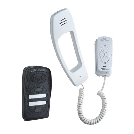
Centurion POLOphone Installation Manual - Page 13
Browse online or download pdf Installation Manual for Intercom System Centurion POLOphone. Centurion POLOphone 17 pages. Entry panel
Also for Centurion POLOphone: Installation Manual (16 pages), Installation Manual (17 pages), Commissioning Procedure (4 pages)

Wiring diagram for poloswitch
Entry panel
1
2
-
+
NO
COM
1
1
2
2
_
_
+
+
NO
NO
COM
COM
Battery supply
Of gate motor
Potential-free normally-
activate gate motor etc.
Two-wire bus with secure signal to operate gate.
Connect power to the POLOphone via the POLOswitch. There is no need to take battery power
to the entry panel.
An alternative solution is to wire TRG and COM to the Aux terminals on the handset PCB.
Group & Volume Settings
Group & Volume Settings
Entry Panel Selector Switch and Volume Control
If the system has only one entry panel set the selector switch (A) to the upper position or (1). Shown
on the next page.
If there are two entry panels set the selector switch on the one panel to the upper position (1) and
on the other panel to the lower position (2).
When adjusting the speech volume start by pressing the call button to activate the speech on the
entry panel.
Rotate the volume control knob (B) in a clockwise direction.
Test the volume by putting the cover back. An acceptable level occurs just before the entry panel howls.
1
-
2
+
NO
COM
1
1
2
2
-
-
NO
NO
Poloswitch
Trig
Ring
Trg
Com
open contact to
Wiring & group/volume settings
1
2
_
3C V3.0
+
AUX
AUX
POLOphone Intercom - Page 13
HANDSET
1
1
2
2
-
-
+
+
NO
NO
COM
COM
1
2
_
Extra
Handsets
+
AUX
AUX
Gate motor
POWER SUPPLY
FOR DOOR STRIKE
Door
Strike
