Major tech MT474 Instruction Manual - Page 8
Browse online or download pdf Instruction Manual for Test Equipment Major tech MT474. Major tech MT474 12 pages. 690v voltage tester

5. OPERATION
5.1. Function test / Self test
Ÿ Test the voltage tester on a known source.
Ÿ Connect test probes. An acoustic sound must be audible and the LED
(8) must be illuminated.
Ÿ The voltage display of the instruments also functions when using
discharged or no batteries.
Ÿ The voltage testers may no longer be used if one or several functions
fails or if no functional reliability can be detected.
Ÿ The instruments are equipped with an internal load enabling the tripping
of an RCD protection device of 10mA or 30mA.
Ÿ For voltage tests (L towards PE) in systems with RCD devices, the RCD
may be triggered. To avoid RCD tripping first test between L and N
(approx. 5s). Immediately afterwards testing L towards PE can be
carried out without RCD tripping.
5.2. Voltage Test
Ÿ Connect both test probes with power source.
Ÿ As from a voltage of >6V the voltage tester switches on automatically.
Ÿ The voltage is displayed via LEDs.
Ÿ For AC voltages the "+" and "-" LEDs are illuminated and an additional
signal sound is audible.
Ÿ For negative voltages the "
additional signal sound is audible.
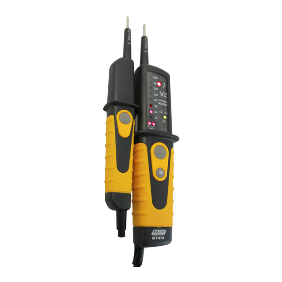
Ÿ The instruments are equipped with an LED row comprising: ±12, 24, 36,
50, 120, 230, 400, 690V AC/DC for DC voltage, the polarity of the
voltage displayed refers to the instrument test probe (+).
Ÿ Due to technical reasons the instrument cannot effectuate an automatic
switch-on for DC voltages within the range of approx. 0V to –/+4.5V.
5.3. Low impedance Test
Without pressing both low impedance buttons, the following voltage steps
(AC or DC) can be indicated: ±24, 36, 50, 120, 230, 400, 690V AC/DC. By
pressing both low impedance push buttons the voltage tester switches to
a lower internal resistance (suppression of inductive and capacitive
voltages). Thus, the indication of low impedance (6) is also activated. The
duration of the test with a lower internal resistance of the device (load
test) depends on the value of the voltage to be measured. To prevent
excessive warming of the voltage tester, it is equipped with a thermal
protection.
5.4. Single-pole phase Test
Ÿ The single-pole phase test is only possible when batteries are installed
and in good condition.
8
" and "-" LEDs are illuminated and an
7
